
Adaptive equipment overload emergency control method based on automatic measure sensitivity identification

An emergency control and automatic identification technology, applied in climate sustainability, information technology support systems, AC network voltage adjustment, etc., can solve problems such as power grid security, equipment overload time interruption, and insufficient online control strategy generation speed.

Active Publication Date: 2017-09-01
NARI TECH CO LTD +5
View PDF2 Cites 3 Cited by
  • Summary
  • Abstract
  • Description
  • Claims
  • Application Information

AI Technical Summary

Problems solved by technology

[0003] However, for a single disconnection or all parallel disconnection of the same station equipment that will not cause overloading of the power grid, since the sensitivity of emergency control measures at different stations may vary and vary with the operating status of other equipment, if the sensitivity of the measures is set offline The scheme of equipment overload connection and switching will inevitably have a serious risk of over-control; if the equipment overload online control scheme based on the sensitivity of online grid state calculation measures is adopted, since it involves the grid online model and the real-time power flow of the grid, when the range of the grid online model and the grid operating state When the estimated accuracy of the method is not enough to fully reflect the sensitivity of the measure to equipment overload, this online control scheme also has a serious risk of over-control, and the generation speed of the online control strategy is not enough to cause the equipment to be disconnected due to the overload time being too long, causing further damage. For serious grid security issues

Method used


Image

  • Adaptive equipment overload emergency control method based on automatic measure sensitivity identification
  • Adaptive equipment overload emergency control method based on automatic measure sensitivity identification
  • Adaptive equipment overload emergency control method based on automatic measure sensitivity identification

Examples


Embodiment 1

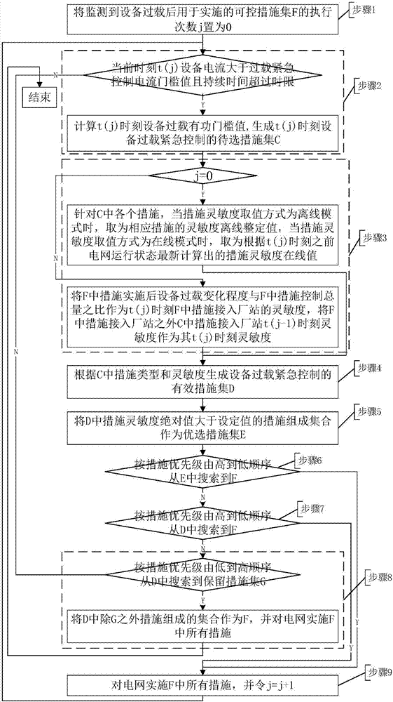
[0046] This embodiment is a kind of implementation mode of the present invention, and its flow process is as follows figure 1 as shown,

[0047] figure 1 Step 1: Set the execution times j of the controllable measure set F used to implement after monitoring the overload of equipment k to 0, and enter step 2;

[0048] figure 1 Step 2: If the current time t j The current of the equipment k current monitoring point is greater than the set equipment overload emergency control current threshold value I cr And the duration exceeds the set time limit t cr (I cr and t cr The value of t should be matched with the current threshold and duration set by the device k over-current protection, so as to prevent the device k over-current protection from acting before its overload emergency control), then set t j The active power and reactive power of the equipment flowing through the current monitoring point k of the equipment at all times are recorded as P j and Q j , the bus voltage ...


PUM


Abstract

The invention discloses an adaptive equipment overload emergency control method based on automatic measure sensitivity identification and belongs to the electric power system safety emergency control technology field. For equipment overload emergency control causing no power grid splitting, e.g., single break or same-station parallel equipment total break, when equipment overload is determined for the first time, equipment overload emergency control measure combinations are calculated according to a measure sensitivity initial value, power grid control is carried out, integrated measure sensitivity is reckoned according to the control effect, the integrated measure sensitivity is utilized to update sensitivity of other measures of a station to which a recently-applied measure is accessed, the equipment overload emergency control measure combinations are calculated, through reckoning sensitivity-calculation control measure iteration, equipment overload is eliminated. The method is advantaged in that control precision, timeliness and reliability are comprehensively guaranteed.

Description

technical field [0001] The invention belongs to the technical field of power system safety emergency control, and more precisely, the invention relates to a method suitable for overload self-adaptive emergency control of power transmission equipment in a power system. Background technique [0002] Factors such as grid power generation, rapid changes in load, or switching on / off of grid equipment may lead to overloading of grid transmission lines and transformers. When the overload is serious, emergency control measures need to be taken to eliminate the overload of transmission equipment. For a single disconnection or parallel equipment with the same station (referring to multiple power transmission equipment with the same or different busbars at each end but connected together only through switches) full disconnection will cause overloading of the equipment that is disconnected from the grid. The sensitivity of the control measures is the same and does not change with the op...

Claims


Application Information

Patent Timeline
IPC IPC(8): H02J3/46H02J3/14
CPCH02J3/14H02J3/46H02J3/0012H02J2310/60Y04S20/222Y02B70/3225
Inventor 徐泰山刘强郑亮罗建裕罗凯明江叶峰金涛查显煜高凯张艳军
Owner NARI TECH CO LTD
Learn More