Ring compression type wireless electric energy transmission system suitable for automatic tool change of ultrasonic machining center

A technology of wireless power transmission and automatic tool change, applied in metal processing equipment, metal processing mechanical parts, circuits, etc. The effect of processing efficiency and improving safety

Pending Publication Date: 2017-09-01
CONPROFE TECH GRP CO LTD +1
View PDF8 Cites 5 Cited by
  • Summary
  • Abstract
  • Description
  • Claims
  • Application Information

AI Technical Summary

Problems solved by technology

Ultrasonic vibration processing of carbon brush power transmission system is prone to rapid carbon brush wear, high heat generation, carbon deposition and fire, and cannot be automatically switched, which is not conducive to product serialization and standardized application
The wireless power transmission part of the wireless power transmission system in traditional ultrasonic vibration machining is disc-shaped. Although this form of power transmission has high efficiency, it cannot display automatic tool change, so it is not conducive to product serialization and standardized applications.

Method used


Image

  • Ring compression type wireless electric energy transmission system suitable for automatic tool change of ultrasonic machining center
  • Ring compression type wireless electric energy transmission system suitable for automatic tool change of ultrasonic machining center
  • Ring compression type wireless electric energy transmission system suitable for automatic tool change of ultrasonic machining center

Examples


Embodiment

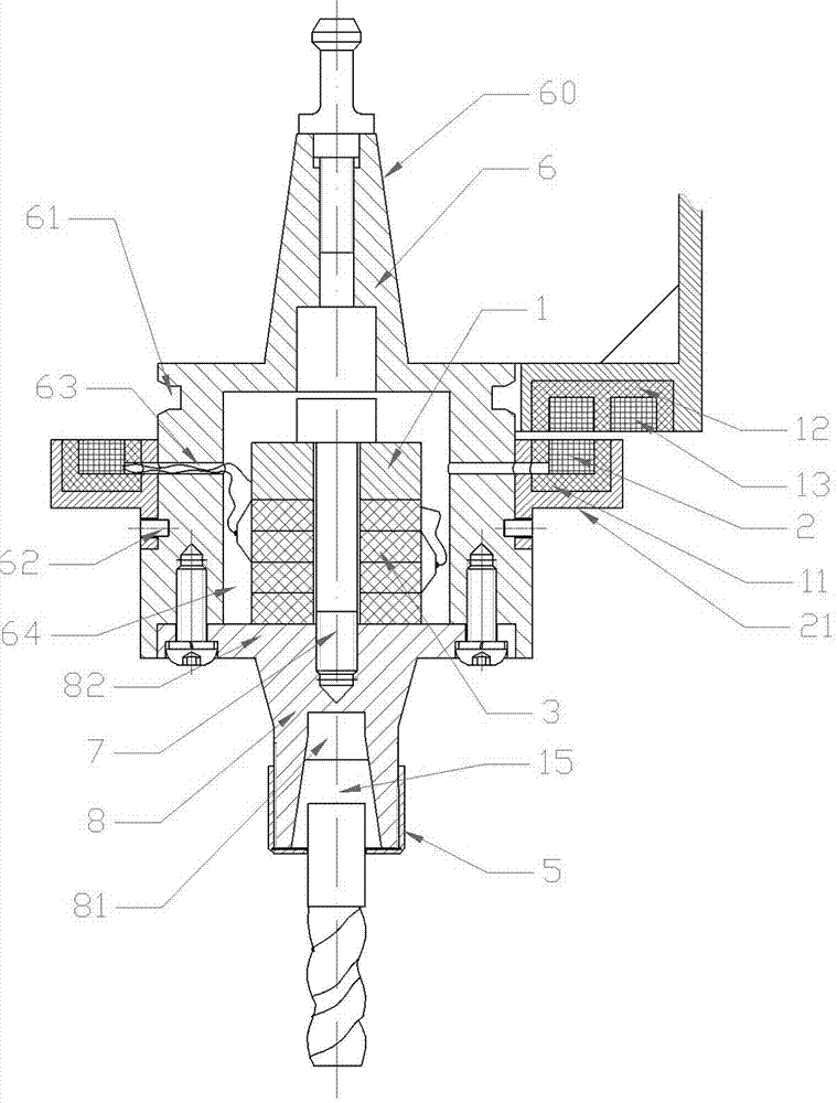
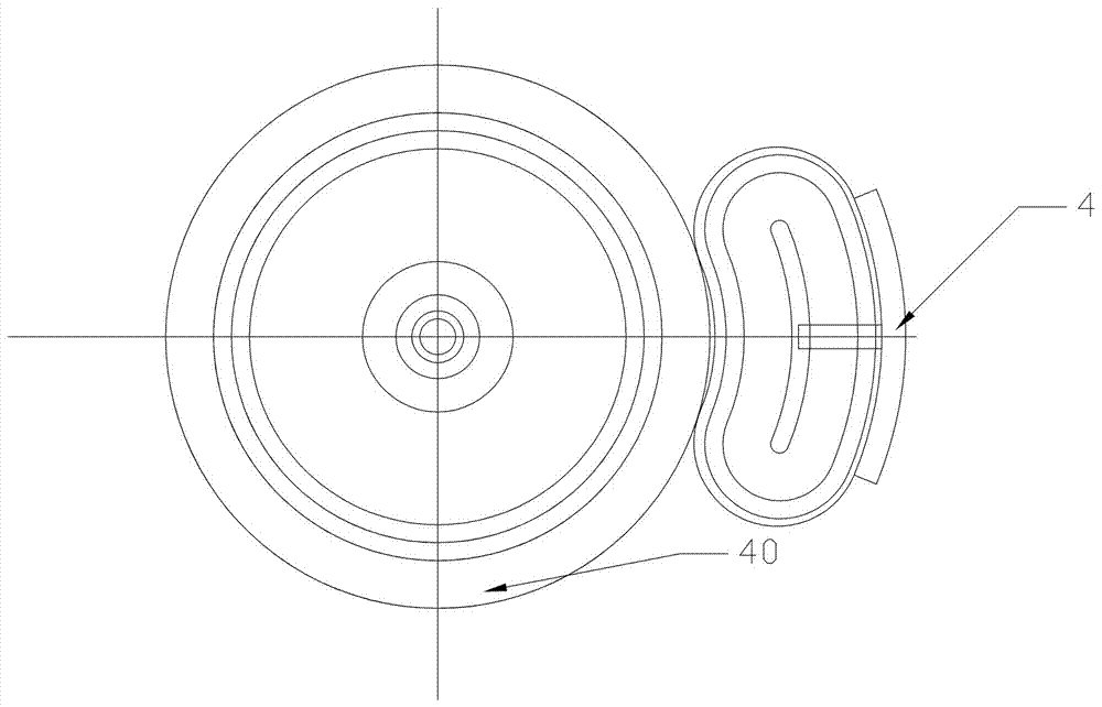
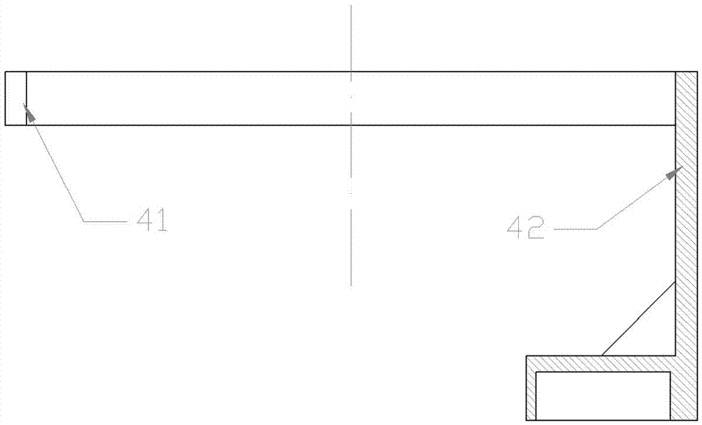
[0028] Example: see figure 1 , in the picture, 1-piezoelectric ceramic pressure plate, 2-disc-shaped power receiving coil, 3-piezoelectric ceramics, 4-quarter disc-shaped power transmitting coil support, 5-lock nut, 6-knife handle , 7-bolt, 8-horn, 11-disc ferrite, 12-quarter disc ferrite, 13-quarter disc power transmitting coil, 15-spring clip Head, 21-Disc-shaped power receiving part, 40-Ferrite fixed tank body, 41-Open ring, 42-Narrow fixed bracket, 60-Holding part, 61-Automatic tool change card slot, 62-Threaded hole, 63-lead hole, 64-cavity, 81-inner tapered hole, 82-flange.

[0029] A ring pressure wireless power transmission system suitable for automatic tool change in ultrasonic machining centers, including tool holder 6, piezoelectric ceramic plate 1, piezoelectric ceramic 3, horn 8, spring collet 15, and quarter disc shape Electric energy transmission coil 13, quarter disk-shaped ferrite 12, disk-shaped electric energy receiving coil 2, disk-shaped ferrite 11 and q...


PUM


Abstract

The invention discloses a ring compression type wireless electric energy transmission system suitable for automatic tool change of an ultrasonic machining center; a disc-shaped electric energy receiving part arranged on a tool holder is internally provided with a disc-shaped ferrite and a disc-shaped electric energy receiving coil; the disc-shaped electric energy receiving part and the tool holder are coaxially arranged; a quarter disc-shaped electric energy emission coil bracket is arranged at the bottom of a spindle shell of the ultrasonic machining center and is provided with a quarter disc-shaped ferrite and a quarter disc-shaped electric energy emission coil; the quarter disc-shaped electric energy emission coil and the disc-shaped electric energy receiving coil are coaxially arranged and are correspondingly overlapped up and down with a mounting gap; the end surfaces of the quarter disc-shaped electric energy emission coil and the disc-shaped electric energy receiving coil are arranged opposite to each other; and a piezoelectric ceramic is fixed on an amplitude varying pole through a piezoelectric ceramic pressure plate and a bolt. In the premise without changing an existing machining center machine tool, the ring compression type wireless electric energy transmission system can conveniently enable the ultrasonic machining center machine tool to satisfy the function of automatic tool change and improves the ultrasonic vibration machining efficiency.

Description

[0001] Technical field: [0002] The invention relates to the field of ultrasonic vibration processing machinery, in particular to a ring pressure wireless power transmission system suitable for automatic tool change in ultrasonic machining centers. [0003] Background technique: [0004] Ultrasonic vibration machining is a processing technology formed by applying high-frequency vibration to the cutting tool or workpiece on the basis of ordinary cutting, grinding, drilling and other processing methods. Compared with ordinary cutting, grinding, and drilling processing methods, ultrasonic vibration processing can reduce the cutting force and cutting heat in the processing process, reduce the amount of tool wear, and improve the quality of the processed surface. It is widely used in hard and brittle materials, vibration materials, etc. Difficult to machine materials. Modern processing technology requires not only processing technology with high precision and high surface quality,...

Claims


Application Information

Patent Timeline
Patent Type & Authority Applications(China)
IPC IPC(8): H02J50/10B23Q3/155H01F38/14
CPCH02J50/10H01F38/14B23Q3/1552B23Q3/15553H01F2038/143B23Q1/0009
Inventor 赵波高国富焦锋向道辉童景琳赵重阳王晓博赵斌斌范凯洋
Owner CONPROFE TECH GRP CO LTD
Why Eureka
Try Eureka