
Aluminum Profile Heavy Machining Center

A technology for machining centers and aluminum profiles, applied in metal processing equipment, metal processing mechanical parts, manufacturing tools, etc., can solve the problems of reducing processing efficiency and automation, limiting processing efficiency and accuracy, and less types of heavy-duty machining centers. To achieve the effect of reasonable design of positioning device, improvement of machining accuracy, and reasonable design of fixtures

Inactive Publication Date: 2016-09-28
EMMEGI SUZHOU
View PDF10 Cites 1 Cited by
  • Summary
  • Abstract
  • Description
  • Claims
  • Application Information

AI Technical Summary

Problems solved by technology

[0002] In the field of aluminum profile processing, there are fewer types of existing heavy-duty machining centers and the machining accuracy is not high
Usually three-axis and manual tool change processing technology is used. The three-axis machining center greatly limits the efficiency and accuracy of processing, and manual tool change also reduces processing efficiency and automation.
Not only that, the existing machining center beams mostly use rigid cylindrical beams as the main structure to support processing, which not only increases the overall weight of the machine, but also tends to deform during use, affecting machining accuracy
Based on the above problems, the existing heavy-duty processing is mostly open, and the safety is not high

Method used


Image

  • Aluminum Profile Heavy Machining Center
  • Aluminum Profile Heavy Machining Center
  • Aluminum Profile Heavy Machining Center

Examples


Embodiment Construction

[0026] The present invention will be further described in detail below in conjunction with the drawings.

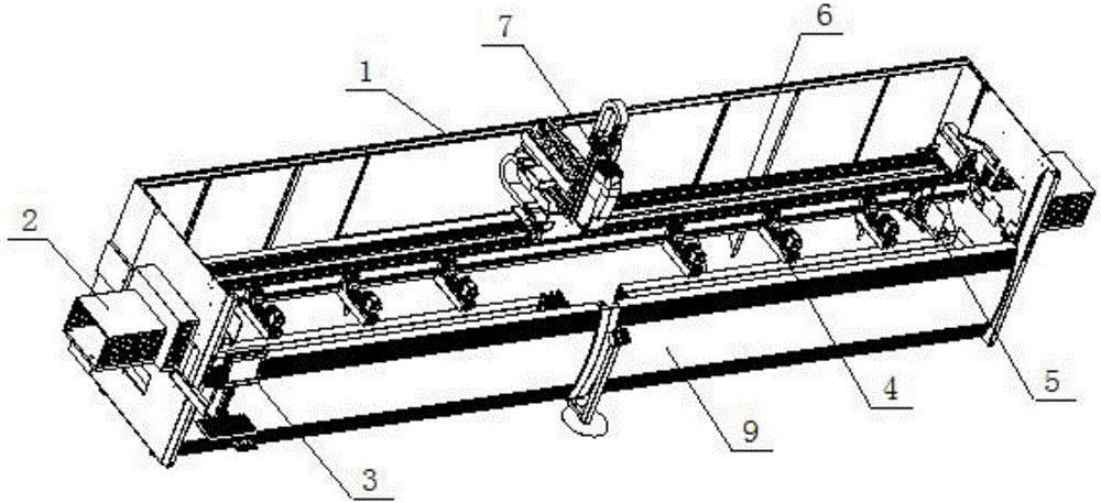
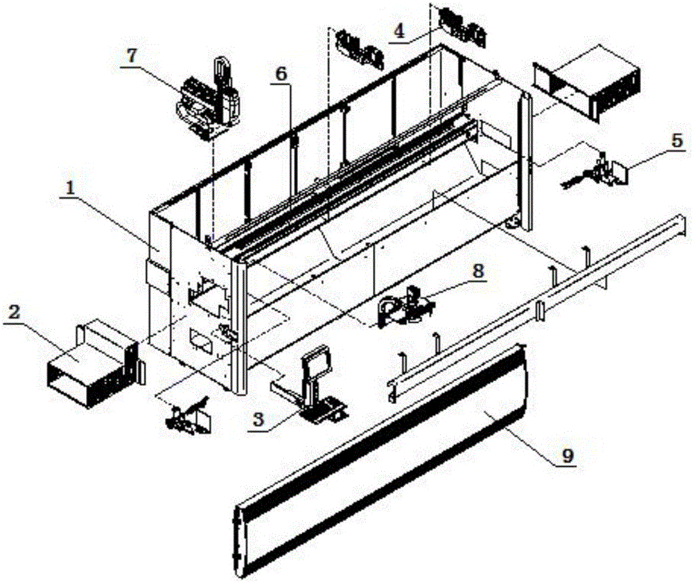
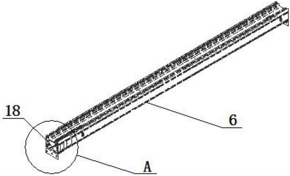
[0027] Refer to figure 1 To Figure 8.

[0028] An aluminum profile heavy-duty machining center, including a fuselage body 1, the left and right sides and the rear side of the fuselage body 1 are provided with shells, and the front side of the fuselage body 1 is an open workbench. The outer side is provided with a PVC protective shell 9, the fuselage body 1 is provided with a feeding support structure 2 at both ends, the fuselage body 1 is provided with a cross beam 6 in the middle position, and the cross beam 6 connects the left and right sides of the fuselage body 1 Shell, the bottom of the beam 6 is provided with a support frame, the left end of the beam 6 is provided with a tool magazine 8 and a spindle portion 7 in sequence, a clamp 4 and a positioning device 5 are provided between the beam 6 and the body 1, so The number of the positioning device 5 is two, and a computer...


PUM


Abstract

The invention relates to a heavy machining center for aluminum profiles, and belongs to the field of aluminum profile machining. The heavy machining center comprises a machine body. Cases are arranged on the left side, the right side and the rear side of the machine body, feeding supporting mechanisms are arranged at the two ends of the machine body, a cross beam is arranged in the middle of the machine body and connected with the cases on the left side and the right side of the machine body, a supporting frame is arranged on the bottom the cross beam, a tool magazine and a main shaft part are sequentially arranged at the left end of the cross beam, and a fixture and a locating device are arranged between the cross beam and the machine body. The machine body is further provided with a computer system. According to the heavy machining center, the aluminum profiles can be machined and treated in the transverse direction or the longitudinal direction or the vertical direction, locating at any angle is achieved through rotation of a fourth shaft, the heavy machining center can change tools automatically, and therefore the machining precision and the machining efficiency are greatly improved.

Description

Technical field [0001] The invention relates to a heavy-duty processing center, belonging to the field of aluminum profile processing. Background technique [0002] In the field of aluminum profile processing, the existing heavy-duty machining centers have fewer types and low machining accuracy. Usually three-axis and manual tool change processing techniques are used. The three-axis machining center greatly limits the processing efficiency and accuracy to a large extent. Manual tool change also reduces the processing efficiency and degree of automation. Not only that, the existing machining center beams mostly use rigid cylindrical beams as the main structure for supporting processing, which not only increases the overall weight of the machine, but also is prone to deformation during use, which affects the processing accuracy. Based on the above-mentioned problems, most of the existing heavy-duty machining is open, and the safety is not high. Summary of the invention [0003] In...

Claims


Application Information

Patent Timeline
Patent Type & Authority Patents(China)
IPC IPC(8): B23Q3/155B23Q1/01B23Q3/00B23Q1/26B23Q11/08
CPCB23Q1/01B23Q1/26B23Q3/00B23Q3/155B23Q11/08
Inventor 保罗弗朗西斯科彼安吉
Owner EMMEGI SUZHOU
Learn More