
Rotary inertia identification method and identification device

A technology of moment of inertia and identification method, which is applied in the field of moment of inertia identification, and can solve problems such as inertia estimation error, torque fluctuation sampling point reduction, and static error of identification results, etc.

Active Publication Date: 2017-09-01
GREE ELECTRIC APPLIANCES INC +1
View PDF6 Cites 5 Cited by
  • Summary
  • Abstract
  • Description
  • Claims
  • Application Information

AI Technical Summary

Problems solved by technology

[0005] In view of this, the present invention discloses a rotational inertia identification method and an identifier to solve the large error in the inertia estimation value in the traditional solution, especially when the sampling rate is low, the torque fluctuation sampling points are reduced, which leads to the identification result A large static difference is generated, which makes the identification effect unsatisfactory

Method used


Image

  • Rotary inertia identification method and identification device
  • Rotary inertia identification method and identification device
  • Rotary inertia identification method and identification device

Examples


Embodiment 1

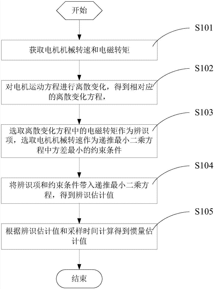
[0100] When the motor motion equation is discretely changed to obtain the corresponding first-order discrete equation, step S102 in the above embodiment specifically includes:

[0101] The motor equation of motion shown in formula (1) is carried out discretization change, obtains the first-order discrete equation as shown in formula (5), and described formula (5) is specifically as follows:

[0102]

[0103] Correspondingly, step S103 specifically includes:

[0104] Select the electromagnetic torque T in the discrete variation equation e as discriminator y k ,y k = ω m [k]-2ω m [k-1]+ω m [k-2], select the motor mechanical speed ω in the discrete variation equation m As a constraint on the minimum variance in the recursive least squares equation ψ k , ψ k =T e [k-1]-T e [k-1].

[0105] In the identification term y k and the constraints ψ k Bring in the recursive least squares equation shown in formula (2) to formula (4) to get the identification estimated value ...

Embodiment 2

[0113] When the motor motion equation is discretely changed to obtain the corresponding second-order discrete equation, step S102 in the above embodiment specifically includes:

[0114] The motor equation of motion shown in formula (1) is carried out discretization change, obtains the second-order discrete equation as shown in formula (7), and described formula (7) is specifically as follows:

[0115]

[0116] Correspondingly, step S103 specifically includes:

[0117] Select the electromagnetic torque T in the discrete variation equation e as discriminator y k ,y k =T e [k-1], select the motor mechanical speed ω in the discrete variation equation m As a constraint on the minimum variance in the recursive least squares equation ψ k ,

[0118] In the identification term y k and the constraints ψ k Bring in the recursive least squares equation shown in formula (2) to formula (4) to get the identification estimated value θ k Afterwards, step S105 in the above embodim...


PUM


Abstract

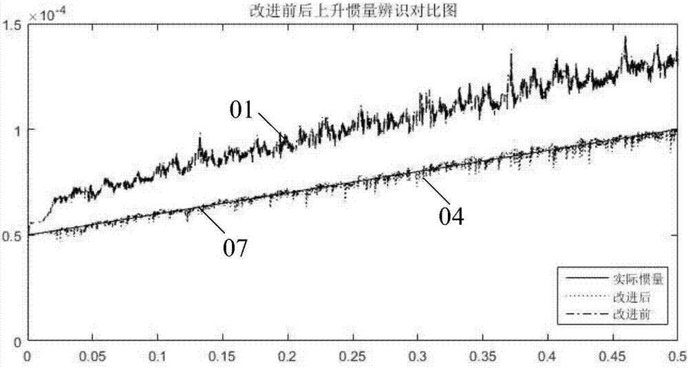
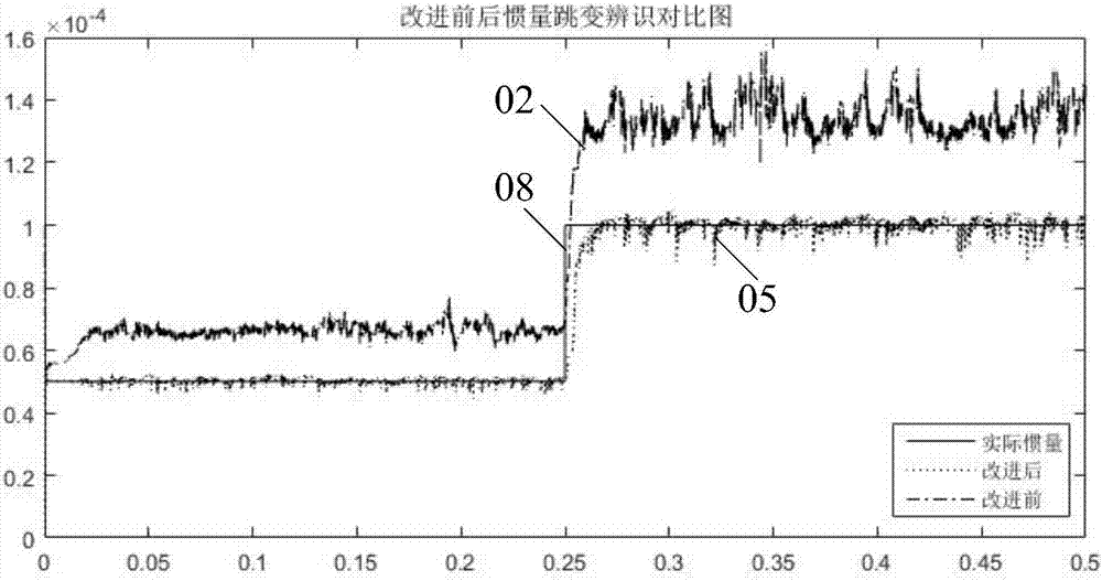
The invention discloses a rotary inertia identification method and an identification device. After the discrete change of a motor motion equation, the electromagnetic torque Te of an obtained discrete change equation is adopted as an identification term yk, and the motor mechanical rotating speed omega m of the discrete change equation is adopted as the minimum constraint condition psi k of a recursive least squares equation. In practice, the fluctuation amplitude of the motor mechanical rotating speed omega m within the unit time is much smaller than the fluctuation amplitude of the electromagnetic torque Te within the unit time, so that the constraint condition psi k is much more stable compared with a traditional scheme. Although the stability of the identification term yk is reduced, the number of participation times of the constraint condition psi k is much larger from the recursive least square equation. Therefore, the accuracy of a finally obtained inertia estimation value is greatly improved according to the identification term yk, the constraint condition psi k and the sampling time Ts. Especially at a low sampling rate, the static difference generated by identification results is greatly reduced. As a result, the accuracy of identification results is improved.

Description

technical field [0001] The present invention relates to the technical field of moment of inertia identification, and more specifically, to a method and an identifier for moment of inertia identification. Background technique [0002] Moment of inertia is the measure of inertia when a rigid body rotates around an axis (the characteristic that a rotating object maintains its uniform circular motion or static), and is represented by the letter I or J. In the servo system, the moment of inertia determines the loop gain of the system, and its change has a great influence on the dynamic performance of the servo system. Therefore, in order to improve the dynamic performance of the servo system, it is necessary to accurately identify the moment of inertia in the servo system. [0003] At present, the methods of moment of inertia identification can be divided into offline inertia identification and online inertia identification, and mainly focus on offline inertia identification. I...

Claims


Application Information

Patent Timeline
Patent Type & Authority Applications(China)
IPC IPC(8): H02P23/14
CPCH02P23/14
Inventor 徐潇许凤霞区均灌王长恺程海珍
Owner GREE ELECTRIC APPLIANCES INC
Learn More