High speed centrifugal atomization device used for metal centrifugal atomization powder preparation

A centrifugal atomization and high-speed centrifugation technology, applied in the field of metal centrifugal atomization pulverizing devices, can solve the problems of short service life and low rotation speed of the centrifugal device, and achieve the effects of reducing production costs, reducing differences, and simplifying structure

Pending Publication Date: 2017-09-05
HUNAN JUTA TECH
View PDF11 Cites 10 Cited by
  • Summary
  • Abstract
  • Description
  • Claims
  • Application Information

AI Technical Summary

Problems solved by technology

The centrifugal atomization device is driven by a steering gear box and a high-speed motor, and its rotation speed is relative

Method used


Image

  • High speed centrifugal atomization device used for metal centrifugal atomization powder preparation
  • High speed centrifugal atomization device used for metal centrifugal atomization powder preparation
  • High speed centrifugal atomization device used for metal centrifugal atomization powder preparation

Examples


Embodiment 1

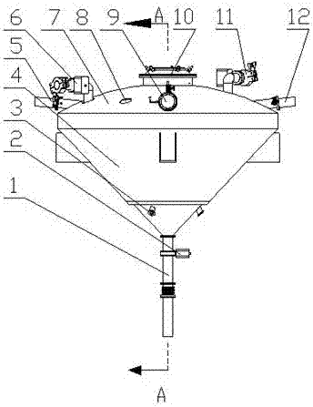
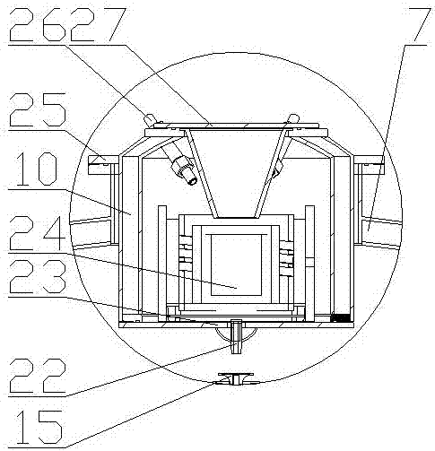
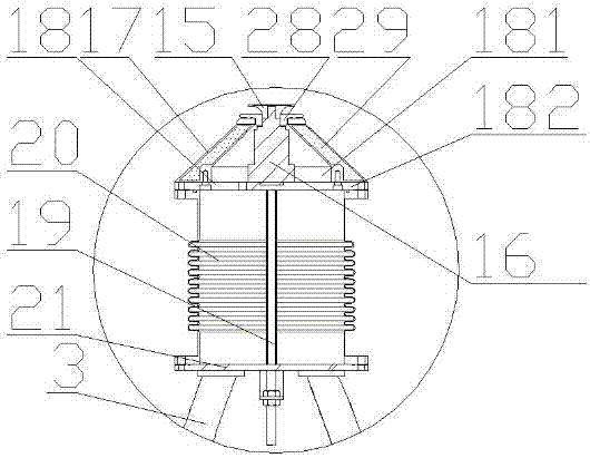
[0038] refer to Figure 1~5 : A high-speed centrifugal atomization device for metal centrifugal atomization powder making in this embodiment, comprising an atomization tank body, a rotating disk 15 and a gas-driven rotating shaft 16; the top center of the atomization tank body is provided with a metal smelting leak bag , the lower end of the side wall is provided with a gas delivery pipe 3 for delivering driving gas to the gas-driven rotating shaft 16, and the bottom is provided with a powder outlet pipe 1; the gas delivery pipe 3 is connected with a high-pressure gas source; the rotating disk 15 is located in the metal smelting Directly below the leak bag, the rotating disk 15 is connected to the top of the gas-driven rotating shaft 16, and is driven by the gas-driven rotating shaft 16 to rotate at a high speed; the maximum rotation of the gas-driven rotating shaft 16 is 80000r / min.

[0039] The air-driven rotating shaft 16 is an air main shaft, and the air main shaft uses co...

Embodiment 2

[0053] refer to Figure 6 , compared with Example 1, a kind of high-speed centrifugal atomization device for metal centrifugal atomization pulverization of the present embodiment has the following differences:

[0054] The high-speed centrifugal atomization device also includes a powder filter 30 in the shape of a truncated cone, and the powder filter 30 is fixed at the middle and lower end of the atomization tank through the gas delivery pipe 3 .

[0055] The working principle and usage method of a high-speed centrifugal atomization device for metal centrifugal atomization powder making in the present invention are as follows: the high-speed centrifugal atomization device melts metal raw materials into a solution through metal smelting leakage; The inert gas is sprayed inside the tank, and the gas blown out from the gas filling port 11 can cool the metal powder after centrifugal atomization, and is also conducive to the efficient dispersion of the metal powder on the rotating...


PUM


Abstract

A high speed centrifugal atomization device used for metal centrifugal atomization powder preparation comprises an atomization tank, a rotary disc and a gas driven rotary shaft. The center of the top of the atomization tank is provided with a metal smelting leakage ladle. The lower end of the side wall of the atomization tank is provided with a gas conveying pipe conveying driving gas to the gas driven rotary shaft. The bottom of the atomization tank is provided with a power outlet pipe. The gas conveying pipe communicates with a high pressure gas source. The rotary disc is located under the metal smelting leakage ladle, connected with the top end of the gas driven rotary shaft and driven by the gas driven rotary shaft to rotate at a high speed. The rotating speed of the gas driven rotary shaft is 50000 r/min or above. The high speed centrifugal atomization device adopts the gas drive rotary shaft, is convenient to mount and is 50000 r/min or above in rotating speed, metal powder prepared through the device is uniform in particle size, and the service life of the device can be up to 10 years or above.

Description

technical field [0001] The invention relates to a metal centrifugal atomization powder making device, in particular to a high-speed centrifugal atomization device for metal centrifugal atomization powder preparation. Background technique [0002] Combining traditional alloy smelting with powder metallurgy, atomization technology provides an important method for preparing common materials and materials with special microstructure and performance requirements. [0003] At present, the centrifugal atomization device used for preparing metal powder at home and abroad includes an atomization chamber. There is a crucible above the atomization chamber. correspond. After the metal is melted by the crucible, it flows to the high-speed rotating atomizing plate through the infusion rod and the liquid outlet nozzle. Under the protection of inert gas, the metal solution is thrown out from the edge of the atomizing plate to form metal powder. [0004] CN 105312587 A discloses a centrifu...

Claims


Application Information

Patent Timeline
IPC IPC(8): B22F9/10
CPCB22F9/10
Inventor 陈雄武王利民
Owner HUNAN JUTA TECH
Why Eureka
Try Eureka