Shaft mechanism emergency maintenance method and structure

An emergency maintenance and shaft technology, applied in the direction of auxiliary equipment, auxiliary welding equipment, welding/cutting auxiliary equipment, etc., can solve problems affecting the normal production and safety of coal mines, delays in production progress, long maintenance periods, etc., to ensure quick recovery The effect of normal production, guaranteed strength and coaxiality, and reduced equipment downtime

Active Publication Date: 2017-09-05
INNER MONGOLIA YITAI COAL
View PDF6 Cites 6 Cited by
  • Summary
  • Abstract
  • Description
  • Claims
  • Application Information

AI Technical Summary

Problems solved by technology
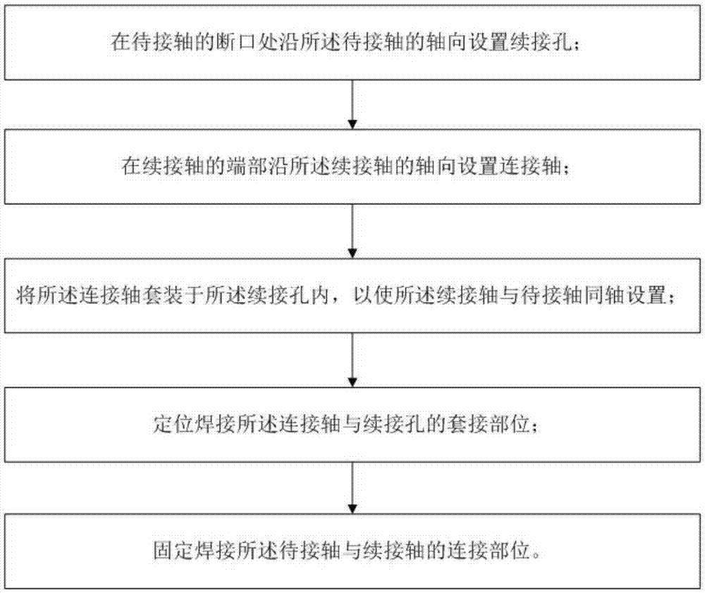
[0002] Under normal circumstances, if large parts such as reducers are damaged in coal mine production, it is only necessary to replace the standby machine in time, but in a few special cases, when the spare machine or spare parts cannot be delivered to the coal mine site in time, serious Affect coal mine production, and even lead to greater safety accidents
[0003] For example, at 5 a.m. on July 12, 2014, the scraper chain of the loader on the 4308 working face of Dadijing Coal Mine, which was in normal production, suddenly stopped running, and the noise inside the connecting cover of the power part was abnormal. The output shaft of the reducer does not rotate, so it is judged that the input shaft of the reducer is broken and the scraper machine stops running
At this time, the 4308 working face is only 3 meters away from the breakthrough, and the roof will have periodic pressure at any time. The working face may be crushed by supports, the equipment cannot be retracted, and the production schedule is severely delayed. Major accidents
Because the spare reducer was being repaired at that time, and the adjacent company did not have a spare reducer of the same type, the delivery time for the original equipment maintenance was at least 30 days, which seriously affected the normal production and safety of the coal mine, and the follow-up maintenance period was very long, which required huge production loss

Method used


Image

  • Shaft mechanism emergency maintenance method and structure
  • Shaft mechanism emergency maintenance method and structure

Examples


Embodiment Construction

[0030] Embodiments of the present invention will be further described in detail below in conjunction with the accompanying drawings and examples. The following examples are used to illustrate the present invention, but should not be used to limit the scope of the present invention.

[0031] In the description of the present invention, unless otherwise specified, "plurality" means two or more. The orientation or positional relationship indicated by the terms "upper", "lower", "left", "right", "inner", "outer", "front end", "rear end", "head", "tail" etc. is Based on the orientation or positional relationship shown in the drawings, it is only for the convenience of describing the present invention and simplifying the description, and does not indicate or imply that the referred device or element must have a specific orientation, be constructed and operated in a specific orientation, and therefore cannot be understood To limit the present invention.

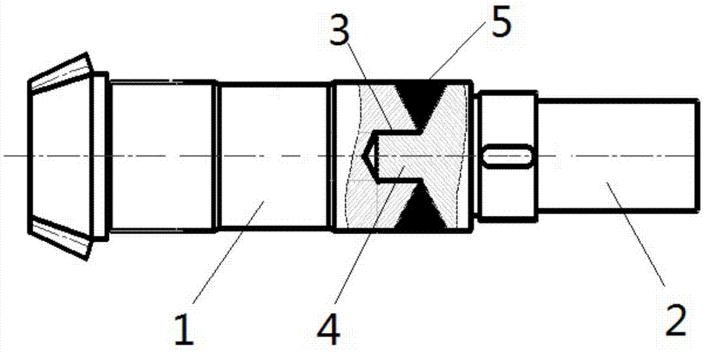
[0032] The emergency maint...


PUM


Abstract

The invention relates to the technical field of coal machine emergency maintenance, in particular to a shaft mechanism emergency maintenance method and structure. The shaft mechanism emergency maintenance method and structure are characterized in that a continuing hole is formed in a fracture of a to-be-connected shaft in the axial direction of the to-be-connected shaft, a connecting shaft is arranged at the end of a continuing shaft in the axial direction of the continuing shaft, the connecting shaft is sleeved with the continuing hole, and therefore it is guaranteed that the continuing shaft and the to-be-connected shaft are coaxial; the continuing shaft is coaxially welded to the fracture of the to-be-connected shaft through two times of welding, it is guaranteed that the to-be-connected shaft obtained after emergency maintenance can quickly restore to normally work, the strength and the coaxiality of maintained shaft mechanisms can be effectively guaranteed, quick maintenance of broken shafts is achieved, the equipment halt time is shortened, and it is guaranteed that a coal mine restores to normally produce as soon as possible; and meanwhile, reusing of the waste shaft mechanisms is achieved, cost is saved, and unnecessary economic losses are reduced.

Description

technical field [0001] The invention relates to the technical field of coal machine emergency maintenance, in particular to an emergency maintenance method and structure of a shaft mechanism. Background technique [0002] Under normal circumstances, if large parts such as reducers are damaged in coal mine production, it is only necessary to replace the standby machine in time, but in a few special cases, when the spare machine or spare parts cannot be delivered to the coal mine site in time, serious Affect coal mine production, and even lead to greater safety accidents. [0003] For example, at 5 a.m. on July 12, 2014, the scraper chain of the loader on the 4308 working face of Dadijing Coal Mine, which was in normal production, suddenly stopped running, and the noise inside the connecting cover of the power part was abnormal. The output shaft of the reducer does not rotate, so it is judged that the input shaft of the reducer is broken and the scraper machine stops running....

Claims


Application Information

Patent Timeline
Patent Type & Authority Applications(China)
IPC IPC(8): B23P6/04B23K31/02B23K37/00
CPCB23K31/02B23K37/00B23P6/04
Inventor 张军庞军林金广清戈保勇孙海军夏文义张宁波聂斌孙文元
Owner INNER MONGOLIA YITAI COAL
Why Eureka
Try Eureka