Equipment for applying ultrasonic cutting to powder feeding type material increase and removal composite manufacturing and machining method

A technology of ultrasonic cutting and processing method, applied in the field of adding and subtracting materials, can solve the problems of heat can not be taken away in time, affecting the tool life of the workpiece machining accuracy and surface quality, can not use cutting fluid and other problems, to achieve novel structure, social Benefit and significant, life-enhancing effect

Inactive Publication Date: 2017-09-05
DALIAN UNIV OF TECH
View PDF8 Cites 14 Cited by
  • Summary
  • Abstract
  • Description
  • Claims
  • Application Information

AI Technical Summary

Problems solved by technology

In addition, because the traditional cutting fluid will affect the additive manufacturing process, the cutting fluid cannot be used in the entire process of adding and subtracting materials, so that the heat generated by cutting cannot be taken away in time, which further increases the temperature rise of the cutting edge of the tool. These problems are all Seriously affect the service life of the tool and the machining accuracy and surface quality of the workpiece in the subsequent material reduction process

Method used


Image

  • Equipment for applying ultrasonic cutting to powder feeding type material increase and removal composite manufacturing and machining method
  • Equipment for applying ultrasonic cutting to powder feeding type material increase and removal composite manufacturing and machining method
  • Equipment for applying ultrasonic cutting to powder feeding type material increase and removal composite manufacturing and machining method

Examples


Embodiment Construction

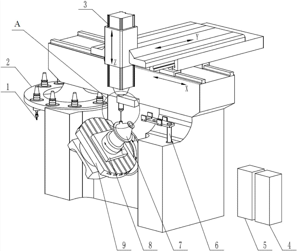
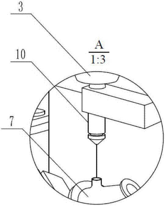
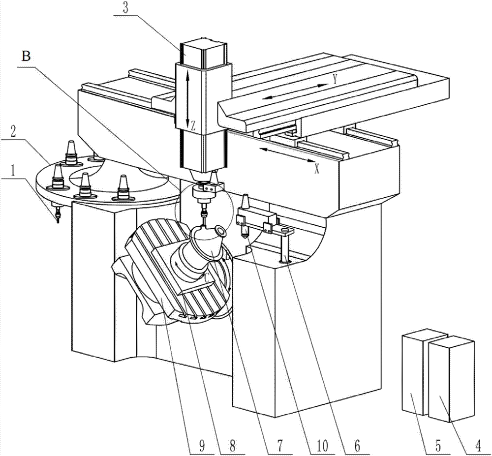
[0035] The specific embodiment of the present invention is shown in the accompanying drawings. The equipment for ultrasonic cutting applied to the compound manufacturing of powder feeding type addition and subtraction materials includes: tool 1, tool magazine 2, spindle 3, bed, laser generator 4, powder feeding device 5 , nozzle bracket 6, substrate 8, workbench 9, cladding nozzle 10 and ultrasonic cutting device; described main shaft 3 is installed on the bed top, and during additive manufacturing, the bottom of main shaft 3 is equipped with cladding nozzle 10, reduces When processing materials, the lower part of the main shaft 3 is equipped with a tool 1, and an ultrasonic cutting device is installed between the main shaft 3 and the tool 1; a cradle-type worktable that can rotate around the horizontal axis and the vertical axis is installed on the bed below the main shaft 3. 9; a base plate 8 is installed on the workbench 9, and the composite manufacturing of the addition and...


PUM


Abstract

The invention relates to the field of material increase and removal manufacturing, in particular to equipment for applying ultrasonic cutting to powder feeding type material increase and removal composite manufacturing and a machining method. The equipment comprises a tool, a tool magazine, a main shaft, a lathe bed, a laser generator, a powder feeding device, a nozzle bracket, a base plate, a working table and a cladding spray head. The main shaft is installed on the upper portion of the lathe bed. In the material increase manufacturing process, the cladding spray head is installed on the lower portion of the main shaft. In the material removal machining process, the tool is installed on the lower portion of the main shaft, and an ultrasonic cutting device is installed between the main shaft and the tool. A cradle type working table capable of rotating around the horizontal axis and the vertical axis is installed on the portion, below the main shaft, of the lathe bed. The base plate is installed on the working table. Workpiece material increase composite manufacturing is carried out on the base plate. The nozzle bracket is installed on the lathe bed and located on one side of the main shaft working table. The nozzle bracket is used for storing the cladding spray head. The cladding spray head is connected with the external laser generator and the powder feeding device. The tool magazine is installed on the other side of the working table, and the tool is installed in the tool magazine. The equipment has the beneficial effects of being novel in structure, easy to machine, high in stability and applicable to various kinds of high-difficulty workpiece machining, prolonging the service life of the tool and improving workpiece machining precision.

Description

technical field [0001] The invention relates to the field of additive and subtractive material manufacturing, in particular to a device and a processing method for applying ultrasonic cutting to powder-feeding additive and subtractive material composite manufacturing. Background technique [0002] The traditional manufacturing process of metal parts mainly removes materials through mechanical subtractive processing methods such as turning and milling, so as to finally obtain parts that meet the quality and precision requirements, which not only wastes materials but also makes it difficult to process parts with complex curved surfaces; additive manufacturing is It is to discretize the three-dimensional entity into several two-dimensional planes, and to produce three-dimensional parts by superimposing materials layer by layer, which can effectively reduce the waste of raw materials, and can process complex parts of any shape. The disadvantage is that the surface quality of the ...

Claims


Application Information

Patent Timeline
Patent Type & Authority Applications(China)
IPC IPC(8): B23P23/04
CPCB23P23/04
Inventor 白倩张璧杨秀轩
Owner DALIAN UNIV OF TECH
Why Eureka
Try Eureka