Heating structure of annealing furnace

A technology of heating structure and annealing furnace, which is applied in the direction of furnace, furnace type, heat treatment furnace, etc., can solve the problems of poor temperature uniformity in the furnace body, short service life of heating tubes, large heating energy consumption of heating tubes, etc., to ensure the annealing effect, Reduce energy consumption and improve thermal insulation effect

Inactive Publication Date: 2017-09-05
昆山金源光电科技有限公司
View PDF5 Cites 1 Cited by
  • Summary
  • Abstract
  • Description
  • Claims
  • Application Information

AI Technical Summary

Problems solved by technology

[0003] However, the heating method of the existing copper wire annealing device is mainly to use heating tubes for heating, which has the following problems: first, the heating energy consumption of the heating tubes is large, which wastes electric energy; second, the heat is relatively concentrated, which makes the temperature uniformity in the furnace body poor, resulting The stress relief effect of the copper wire is poor, resulting in uneven annealing of the copper wire; third, the heating tube has a short service life and needs to be replaced frequently, which not only affects production, but also consumes materials and increases production costs

Method used


Image

  • Heating structure of annealing furnace
  • Heating structure of annealing furnace

Examples


Embodiment

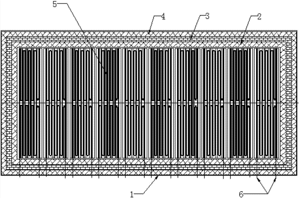
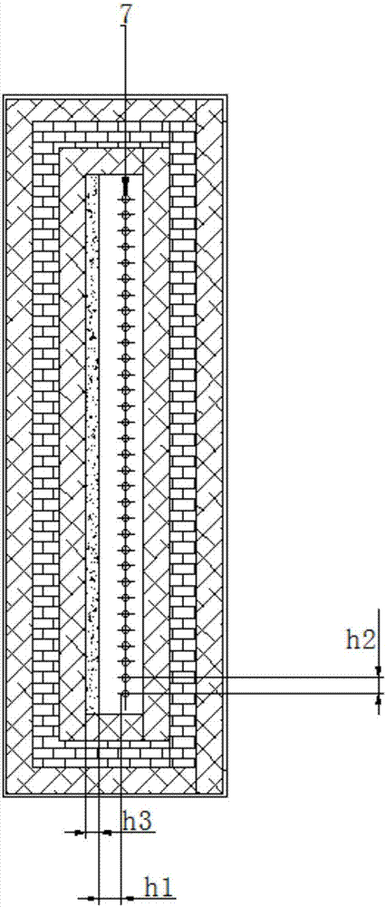
[0030] Embodiment: a kind of heating structure of annealing furnace, as Figure 1 to Figure 2 As shown, the annealing furnace includes a furnace body, the furnace body is provided with a heating structure, and the furnace body includes a shell 1 and an insulation layer located on the inner wall of the shell, with the center of the furnace body as the inside, The thermal insulation layer is provided with three layers, and from the inside to the outside is the first thermal insulation layer 2, the second thermal insulation layer 3 and the third thermal insulation layer 4, and the two adjacent thermal insulation layers are seamlessly bonded;

[0031] The heating structure includes a plurality of electric furnace reels 5 located inside the furnace body and heating wires 6 corresponding to and connected to the electric furnace reels one by one, and the number of groups of the heating wires is the same as that of the electric furnace reels. The numbers are equal, the electric furnac...


PUM

PropertyMeasurementUnit
thicknessaaaaaaaaaa
thicknessaaaaaaaaaa
thicknessaaaaaaaaaa

Abstract

The invention discloses a heating structure of an annealing furnace. The heating structure is arranged in a furnace, the furnace comprises a shell and three heat-insulation layers, the heat-insulation layers are positioned on the inner wall of the shell, and every two adjacent heat-insulation layers seamlessly tightly cling to each other. The heating structure comprises a plurality of electric furnace heating wire discs and heating wires, the heating wires are in one-to-one correspondence with the electric furnace heating wire discs and are connected with the electric furnace heating wire discs, the group number of heating wires is equal to the number of the electric furnace heating wire discs, and the multiple electric furnace heating wire discs are parallelly arranged along the length direction of the furnace at intervals; each group of heating wires comprises two single wires, the two single wires of each group of heating wires are connected with two ends of the corresponding electric furnace heating wire disc, and the heating wires are mounted in furnace disc holes of the shell and are nickel-chromium wires; a plurality of annealing furnace tubes are further arranged in the furnace, and to-be-annealed wires can pass the annealing furnace tubes. The heating structure has the advantages the inside of the furnace can be uniformly and stably heated, accordingly, the wires can be uniformly and stably annealed, and good stress relief effects can be realized; the inside of the furnace is heated by the nickel-chromium wires, and accordingly the heating structure is low in energy consumption, long in service life and low in cost; the furnace is excellent in heat-insulation performance, and accordingly energy consumption further can be reduced.

Description

technical field [0001] The invention belongs to the technical field of an annealing furnace structure for heat treatment, and in particular relates to a heating structure of an annealing furnace for copper wires. Background technique [0002] Copper wire is the main component of various cables. Residual stress will be generated in the production process of existing copper wire. In order to improve its performance, it is necessary to add an annealing process to eliminate this residual stress. [0003] However, the heating method of the existing copper wire annealing device is mainly to use heating tubes for heating, which has the following problems: first, the heating energy consumption of the heating tubes is large, which wastes electric energy; second, the heat is relatively concentrated, which makes the temperature uniformity in the furnace body poor, resulting The stress relief effect of the copper wire is poor, resulting in uneven annealing of the copper wire; third, the...

Claims


Application Information

Patent Timeline
Patent Type & Authority Applications(China)
IPC IPC(8): C21D1/26C21D1/40C21D9/62C22F1/08
CPCC21D1/26C21D1/40C21D9/562C21D9/62C22F1/08
Inventor 王重真谭思平
Owner 昆山金源光电科技有限公司
Why Eureka
Try Eureka