Wheel train energy storage power generation device

A power generation device and energy storage technology, which is applied in the direction of transmission, engine, machine/engine, etc., can solve the problems of only 120km/h maximum speed, reduced driving torque, unsuitable for electric vehicles, etc., to reduce heat, prolong life, improve The effect of high temperature resistance

Inactive Publication Date: 2017-09-05
NINGBO LITAI ELECTRONICS TECH
View PDF5 Cites 0 Cited by
  • Summary
  • Abstract
  • Description
  • Claims
  • Application Information

AI Technical Summary

Problems solved by technology

[0002] In recent years, electric vehicles have been developing continuously, but the current maximum range of electric vehicles is less than 120km, and the maximum speed is only 120km per hour.
The outer ring power generation mechanism and the inner ring power generation mechanism are double-rotor double-stator conjugate power generation devices. The double-stator coils are reversely wound, and the positive and negative torques generated during operation are offset, which greatly reduces the driving torque and uses a small The driving force generates relatively large power, which saves energy and increases the power output, so as to realize energy-saving and high-efficiency power generation. However, the power generation device of this invention is not only costly, but also limited by space, so it is not suitable for use on electric vehicles.

Method used


Image

  • Wheel train energy storage power generation device
  • Wheel train energy storage power generation device
  • Wheel train energy storage power generation device

Examples


Embodiment 1

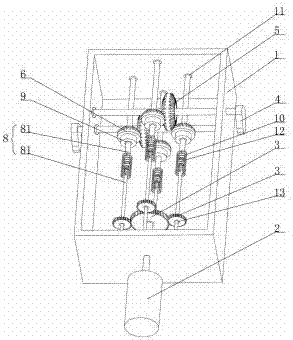
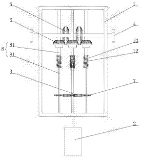
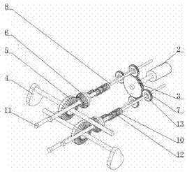
[0023] like Figure 1-4 As shown, a gear train energy storage power generation device includes a gearbox body 1, a generator 2 connected to the gearbox body 1, and a drive assembly is arranged in the gearbox body 1, including an eccentric weight 4, a disk gear 5, a cone Shaped gear 6 and driven gear 7, the eccentric weight 4 is coaxially connected with the disk gear 5, the front and back sides of the disk gear 5 are provided with teeth, and the front and back sides of the disk gear 5 are meshed with a bevel gear 6, the cone The gear 6 is coaxially connected with the driven gear 7 through the rotating shaft 8, and the driven gear 7 is meshed with the power generation gear 3. The power generation gear 3 is installed on the main shaft of the generator 2, and the bevel gear 6 has a built-in one-way lock with the same locking direction. Bearing one 9 and one-way bearing one 9 are set on the corresponding rotating shaft 8, a cavity 401 is arranged in the eccentric weight 4, and a ro...

Embodiment 2

[0034] like Figure 1-4 As shown, a gear train energy storage power generation device includes a gearbox body 1, a generator 2 connected to the gearbox body 1, and a drive assembly is arranged in the gearbox body 1. There are two sets of drive assemblies, and the two sets of drive assemblies are in the form of Relatively arranged, including eccentric weight 4, disk gear 5, bevel gear 6 and driven gear 7, the eccentric weight 4 is coaxially connected with the disk gear 5, the front and back of the disk gear 5 are provided with teeth, the disk gear 5 There are bevel gears 6 meshed on the positive and negative sides of the shaft, and the bevel gears 6 are coaxially connected with the driven gears 7 through the rotating shaft 8. The driven gears 7 are meshed with the generator gears 3, and the generator gears 3 are installed on the main shaft of the generator 2. , the bevel gears 6 have built-in one-way bearings-9 with the same locking direction, and the one-way bearings-9 are sle...


PUM


Abstract

The invention provides a wheel train energy storage power generation device which comprises a gearbox body and a power generator connected with the gearbox body; driving components are arranged in the gearbox body, and comprise eccentric weights, disc face gears, bevel gears and driven gears; the eccentric weights are coaxially connected with the corresponding disc face gears; teeth are formed on the front and back faces of each disc face gear; the positive and negative faces of each disc face gear are engaged with the corresponding bevel gears; the bevel gears are coaxially connected with the driven gears through rotating shafts correspondingly; the driven gears are engaged with a power generation gear; the power generation gear is arranged on a spindle of the power generator; first one-way bearings having the same locking direction are built in the corresponding bevel gear, and sleeve the corresponding rotating shafts; and balls are arranged in the corresponding eccentric weights. By employing the eccentric gravity and the inertia dynamic action in a vehicle travelling process, the eccentric weights are driven to swing front and back, and the power generator is driven to generate electricity by transmission components like the disc face gears, the bevel gears, the driven gears and the power generation gear, so that the purpose of travelling and charging at the same time is realized.

Description

technical field [0001] The invention relates to the technical field of power generation, in particular to a gear train energy storage power generation device. Background technique [0002] In recent years, electric vehicles have been developing continuously, but the current maximum range of electric vehicles is less than 120km, and the maximum speed is only 120km per hour. The hassle of frequent charging is the biggest obstacle to the development of electric vehicles. Some people are already considering applying solar technology to electric vehicles. [0003] In the existing technical field of power generation, for example, a power generation device, CN105429404A, this invention discloses a power generation device, including a coaxial and nested inner ring power generation mechanism and an outer ring power generation mechanism; the inner ring power generation mechanism The rotor and the rotor of the outer ring generator mechanism are all fixed on the same rotating shaft of...

Claims


Application Information

Patent Timeline
Patent Type & Authority Applications(China)
IPC IPC(8): F03G3/00F03G7/08F16H33/08
CPCF03G3/00F03G7/08F16H33/08
Inventor 叶力谢超
Owner NINGBO LITAI ELECTRONICS TECH
Why Eureka
Try Eureka