
Method and circuit for treating echo signal of low-power ultrasonic flowmeter

An echo signal and ultrasonic technology, which is applied in the echo signal processing method and circuit field of low-power ultrasonic flowmeters, can solve the problems of reduced accuracy, difference in ultrasonic propagation sound path, and susceptibility to interference, etc., to reduce waveform changes , Consistent signal strength and reduced power consumption

Pending Publication Date: 2017-09-05
CHINA JILIANG UNIV
View PDF11 Cites 11 Cited by
  • Summary
  • Abstract
  • Description
  • Claims
  • Application Information

AI Technical Summary

Problems solved by technology

This method can only roughly measure the propagation time, which will lead to a decrease in accuracy. At the same time, the same magnification will affect the waveform of the echo signal, and the change of the envelope waveform will introduce new measurement errors.
[0005] The other is to set a single threshold, and compare the echo first wave signal with the threshold voltage to obtain a square wave signal. At this time, the arrival time of the first square wave is used as the flight time of the ultrasonic signal. This method is easily affected by interference.
In addition, there are vortices in the gas flow, which will cause differences in the sound path of ultrasonic waves at the same gas flow rate
Since the ultrasonic flowmeter has the characteristics of high precision and high repeatability, if the echo signal is processed improperly, the accuracy and repeatability of the flowmeter will decrease, and even the measurement task cannot be completed.

Method used


Image

  • Method and circuit for treating echo signal of low-power ultrasonic flowmeter
  • Method and circuit for treating echo signal of low-power ultrasonic flowmeter
  • Method and circuit for treating echo signal of low-power ultrasonic flowmeter

Examples


Embodiment Construction

[0019] A low-power ultrasonic flowmeter echo signal processing method and circuit proposed by the present invention will be further described below in conjunction with the accompanying drawings.

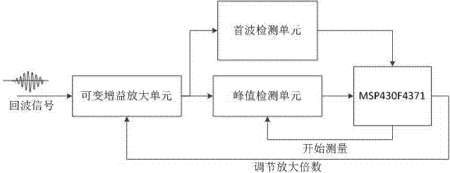
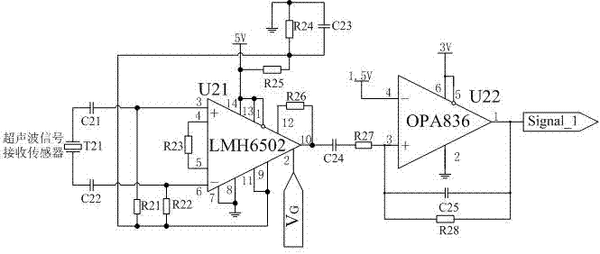
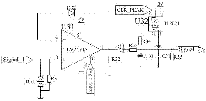
[0020] refer to figure 1 , the frame structure of the whole system is to amplify the received echo signal in the variable gain amplifier unit, the amplified signal is converted into a square wave by the first wave detection unit and then transmitted to the single-chip unit, and the single-chip unit receives the square wave signal , enable the peak detection unit to perform peak detection, and compare the detected peak value to the single-chip unit with the set voltage value to control the amplification factor of the variable gain amplification unit until the detected sampling signal is within the set range, and the single-chip unit Time T from sending the ultrasonic signal to the rising edge of the square wave incoming from the first wave unit 1 and the time T from sending the ultra...


PUM


Abstract

The invention discloses a method and a circuit for treating an echo signal of a low-power ultrasonic flowmeter. The circuit comprises a variable gain amplifying unit, a peak detection unit, a head wave detection unit and a single chip unit. The method for treating the echo signal of the low-power ultrasonic flowmeter, disclosed by the invention, comprises the following steps: utilizing head wave detection to accurately judge if receiving an echo; controlling the peak detection unit to enable and perform echo peak value measurement; comparing an AD value acquired through the peak value detection with a preset voltage value scope; adjusting an amplification factor to guarantee the consistency of the measured echo signal, thereby reducing the influence of different amplification factors on the waveform and reducing the power consumption of the circuit.

Description

technical field [0001] The invention belongs to the technical field of flow detection, and relates to a low-power-consumption ultrasonic flowmeter echo signal processing method and a circuit. Background technique [0002] As the government accelerates the trend of building a resource-saving and environment-friendly society, flow measurement has also begun to move towards high precision, high repeatability, and low pressure loss. Compared with other flowmeters, the ultrasonic flowmeter has the above characteristics. [0003] Ultrasonic flowmeters generally use the time difference method for flow measurement, that is, use two ultrasonic transducers upstream and downstream to transmit ultrasonic signals, measure the time when the other transducer receives the ultrasonic signal, the difference between the two times and the pipeline related to the fluid flow rate. However, due to the large acoustic impedance of the gas, the propagation of the ultrasonic signal in the gas is sev...

Claims


Application Information

Patent Timeline
Patent Type & Authority Applications(China)
IPC IPC(8): G01F1/66G01F15/00G05B19/042H03F3/68G01R29/027G01R19/04
CPCH03F3/68G05B19/042G05B19/0423G01F1/667G01F15/00G01R19/04G01R29/0276G05B2219/21137G05B2219/21063
Inventor 赵伟国章涛虞结勇
Owner CHINA JILIANG UNIV
Learn More