

Building construction site efficient disinfectant spraying device
A technology for building construction and spraying devices, which is applied in the direction of liquid spraying devices, spraying devices, etc., can solve the problems that the disinfectant cannot achieve the disinfection and sterilization effect, cannot achieve effective spraying of the disinfectant, and the spraying effect of the disinfectant is poor. Disinfection and sterilization effect, which is beneficial to give full play and improve the effect of disinfection effect
- Summary
- Abstract
- Description
- Claims
- Application Information
AI Technical Summary
Problems solved by technology
Method used
Image

Examples
Embodiment Construction
[0018] Below in conjunction with specific embodiment, the technical scheme of this patent is described in further detail:
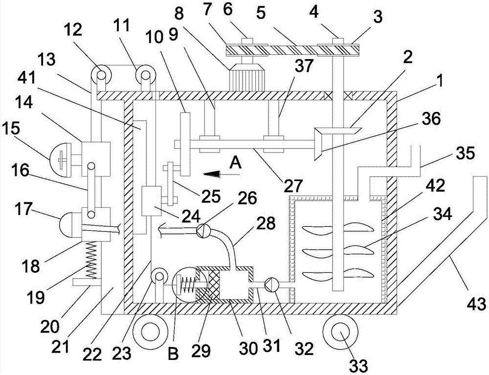
[0019] see Figure 1-3 , a high-efficiency spraying device for disinfectant on a building construction site, comprising a car body 1, a driving motor 8 is fixedly installed on the top of the car body 1, the motor shaft of the driving motor 8 is fixedly installed with a drive shaft 6 through a coupling, and the drive shaft 6 A driving pulley 7 is fixedly installed on the upper coaxial line; a stirring shaft 4 is vertically rotated inside the car body 1, and a driving bevel gear 2 is fixedly installed on the stirring shaft 4, and the stirring shaft 4 runs through the upper side of the car body 1 upwards wall, the upper end of the stirring shaft 4 is coaxially fixed with a driven pulley 3, and the driven pulley 3 is connected to the driving pulley 7 through a transmission belt 5; the vehicle body 1 is provided with a liquid storage tank 42, and the stirring ...
PUM
 Abstract
Description
Claims
Application Information