
Button dyeing machine

A technology for dyeing machines and buttons, applied in the field of button dyeing machines, can solve the problems of uneven dyeing, high labor intensity of workers, and low button dyeing efficiency.

Inactive Publication Date: 2017-09-08
嘉兴瑜浩服饰辅料有限公司
View PDF7 Cites 2 Cited by
  • Summary
  • Abstract
  • Description
  • Claims
  • Application Information

AI Technical Summary

Problems solved by technology

The first clothes of human beings were made of animal skins, and the earliest "fabric" wrapped around the body was made of hemp fiber and grass. The definition of clothing in the national standard is that clothes are worn on the human body to protect and decorate the product. Also known as clothes, in today's society, clothing is already a must for everyone to decorate themselves, protect themselves, and give themselves and their families. It is not only for wearing, but also an identity, an attitude towards life, and an expression of personal charm. , most of the clothes are equipped with buttons, the buttons not only make the clothes easy to put on and take off, but also make the clothes more beautiful, most of the buttons are pressed into button-sized metal blocks on the metal plate with a button pressing machine during the production process , and then the metal block is polished, dyed, engraved, drilled and other processes to make finished buttons. The existing button dyeing machines have the disadvantages of low dyeing efficiency of buttons, uneven dyeing, and high labor intensity of workers.

Method used


Image

  • Button dyeing machine

Examples


Embodiment Construction

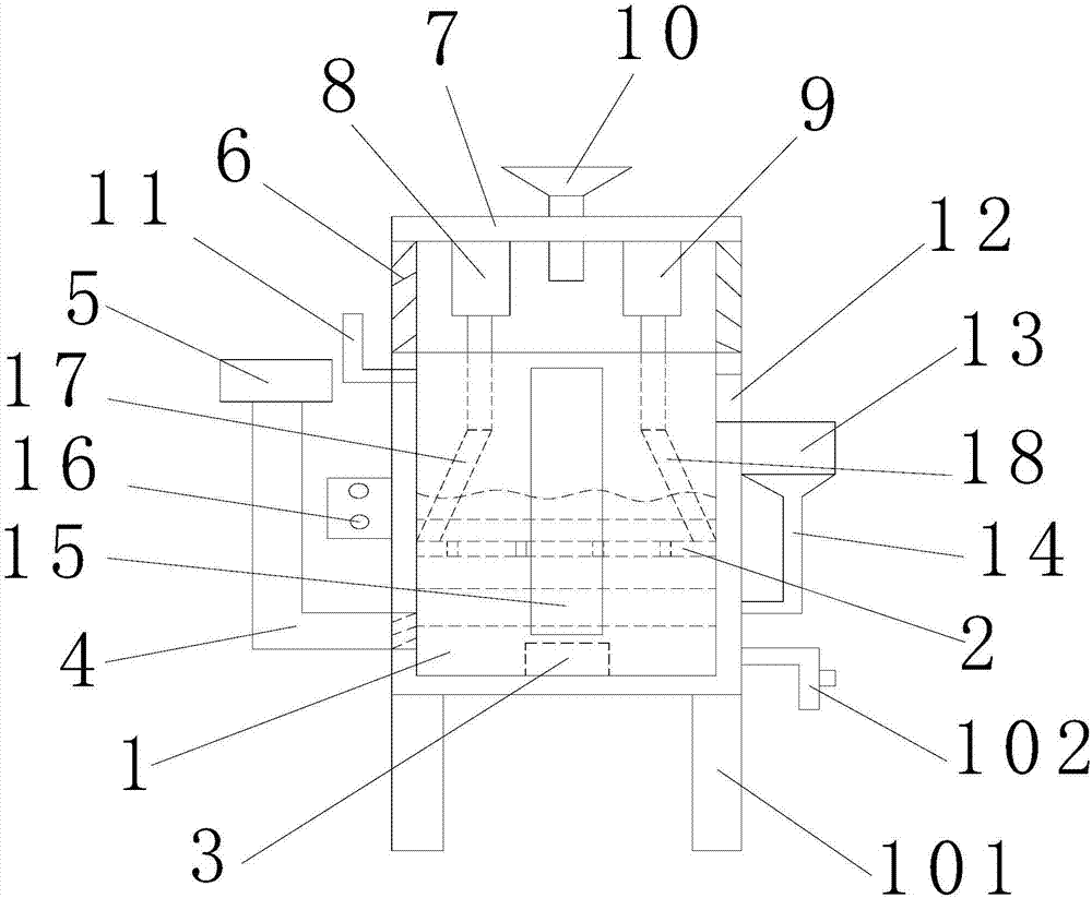
[0022] refer to figure 1 , a button dyeing machine of the present invention comprises a dyeing vat 1, a material sieve 2, an electric heater 3, an air intake pipe 4, an air pump 5, a mounting frame 6, a top plate 7, a first cylinder 8, a second cylinder 9, a lower hopper 10, Dye injection pipe 11, discharge port 12, draining box 13, conduit 14, observation window 15, first connecting rod 17 and second connecting rod 18, the inner side of the dyeing vat 1 is slidingly provided with a horizontally arranged material sieve 2 , the inner bottom of the dyeing vat 1 is provided with an electric heater 3, the lower side of the dyeing vat 1 is connected with an air intake pipe 4, and the outer end of the air intake pipe 4 is provided with an air pump 5, and the two sides of the upper part of the dyeing vat 1 Two symmetrically arranged mounting frames 6 are fixedly arranged, and a horizontally arranged top plate 7 is fixedly connected between the upper ends of the two mounting frames. ...


PUM


Abstract

The invention discloses a button dyeing machine. The button dyeing machine comprises a dye vat, a containing sieve, an electric heater, an air inlet pipe, an air pump, mounting racks, a top plate, a first air cylinder, a second air cylinder, a discharging hopper, a dye injection pipe, a discharge opening, a draining box, a guide pipe, an observation window, a first connecting rod and a second connecting rod. The horizontally-arranged containing sieve is arranged on the inner side of the dye vat in a sliding manner. The electric heater is arranged at the bottom of the inner side of the dye vat. The lower side of the dye vat communicates with the air inlet pipe. The air pump is arranged at the outer end of the air inlet pipe. The two symmetrically-arranged mounting racks are fixedly arranged on the two sides of the upper portion of the dye vat. The horizontally-arranged top plate is fixedly connected between the upper ends of the two mounting racks. The first air cylinder and the second air cylinder arranged side by side left and right are fixedly arranged at the bottom of the top plate. Compared with the prior art, buttons can be dyed fast and efficiently; the button dyeing efficiency and effect are improved; the labor intensity of workers is reduced; and great convenience is brought to button production.

Description

[0001] 【Technical field】 [0002] The invention relates to the technical field of garment accessories processing equipment, in particular to a button dyeing machine. [0003] 【Background technique】 [0004] Clothing, generally refers to the general term of clothes, shoes, bags, toys, accessories, etc., mostly refers to clothes. Clothes have appeared in the early stages of the development of human society. Ancient people made rough "clothes" from various materials they could find around them for body protection. The earliest clothes of human beings were made of animal skins, and the earliest "fabric" that wrapped the body was made of hemp fiber and grass. The definition of clothing in the national standard is that clothes are worn on the human body to protect and decorate products. Also known as clothes, in today's society, clothing is already a must for everyone to decorate themselves, protect themselves, and give themselves and their families. It is not only for wearing, but ...

Claims


Application Information

Patent Timeline
IPC IPC(8): B05C3/02B05C13/02B05C11/10B05C9/12
CPCB05C3/02B05C9/12B05C11/10B05C11/1042B05C13/02
Inventor 章永伟
Owner 嘉兴瑜浩服饰辅料有限公司
Learn More