Milling machining method for wave-transmitting ceramic antenna window

A ceramic antenna and milling processing technology, which is applied in the direction of stone processing tools, stone processing equipment, manufacturing tools, etc., can solve the problems of poor processing quality, edge damage, high scrap rate, etc., and achieve the effect of improving the quality of the processed surface

Active Publication Date: 2017-09-08
HARBIN UNIV OF SCI & TECH +1
View PDF8 Cites 8 Cited by
  • Summary
  • Abstract
  • Description
  • Claims
  • Application Information

AI Technical Summary

Problems solved by technology

[0007] The purpose of the present invention is to overcome the problems of low milling efficiency, high reject rate and poor processing quality of the current wave-transparent ceramic antenna window, and provide a milling method for the wave-transparent ceramic antenna window, which can realize the wave-transparent ceramic antenna window There are no pits, microscopic cracks, edge damage, hole chipping and other damage on the processed surface, which is sufficient to meet the working requirements of wave-transparent ceramic antenna windows

Method used


Image

  • Milling machining method for wave-transmitting ceramic antenna window
  • Milling machining method for wave-transmitting ceramic antenna window
  • Milling machining method for wave-transmitting ceramic antenna window

Examples


Embodiment Construction

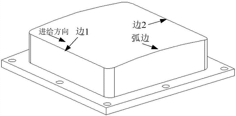
[0021] Since the wave-transparent ceramic antenna window is often made of wave-transparent Si3N4 ceramic material, its typical structural parameters are: refer to figure 1 , the outside is a stepped structure, the size of the upper step is 106mm×106mm, and the surface is curved; the size of the lower step is 134mm×1334mm, the interior is a cavity, and there are 8 Φ6mm through holes on the lower step, so the following Taking the structural parameters and the wave-transmitting Si3N4 ceramic material as an example, the specific implementation of the present invention will be described in detail.

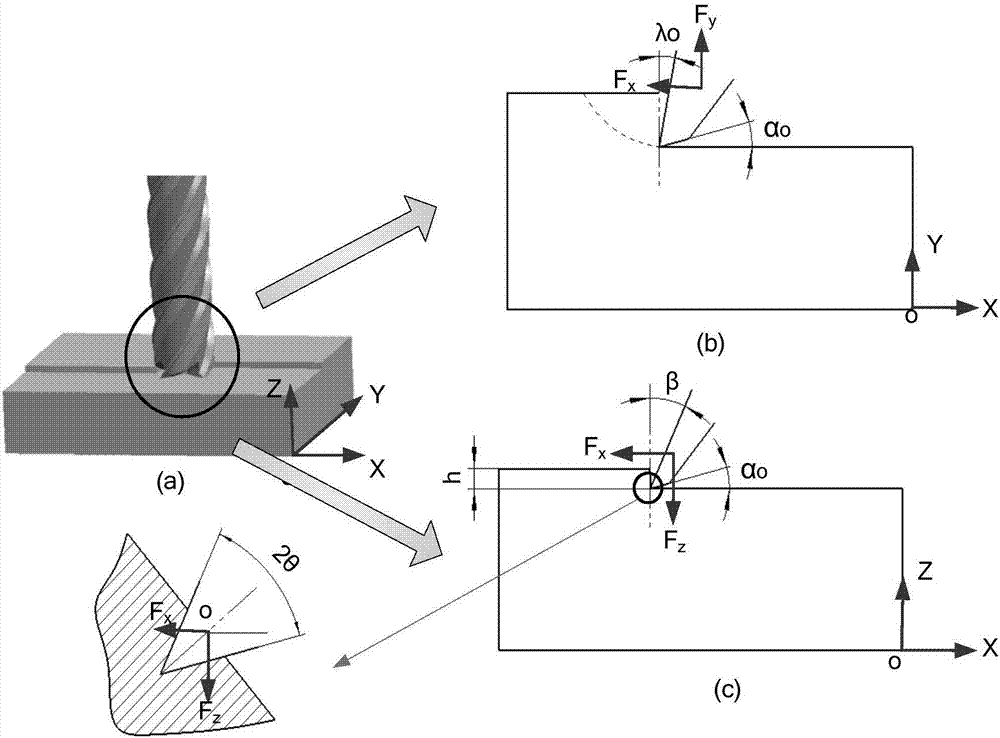
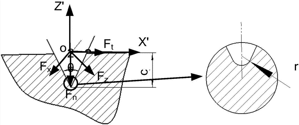
[0022] 1. Calculating the critical milling depth: the schematic diagram of the planar milling process of the wave-transparent ceramic antenna window is as follows figure 2 As shown in (a), the contact relationship between the cutting edge of the tool and the workpiece is as follows figure 2 As shown in (b) and (c), through coordinate transformation, after transforming XOZ coordinates...


PUM

PropertyMeasurementUnit
elastic modulusaaaaaaaaaa
hardnessaaaaaaaaaa

Abstract

The invention discloses a milling machining method for a wave-transmitting ceramic antenna window and aims to solve the problems that existing wave-transmitting ceramic antenna windows are low in milling machining efficiency, high in rejection rate and poor in machining quality. The method is technically characterized by comprising the steps as follows: 1, the contact relationship between a cutting edge of a tool and the surface of a workpiece is obtained; the stress field intensity of the tip of the cutting edge of the tool is solved, the critical milling depth is obtained, and then machining process parameters of the workpiece are determined according to the critical milling depth; 2, the machining path of tool follows the principle that different tool path plans are adopted for different machining areas on the same plane, and the shearing stress on the machining edge points to the inside of a material; 3, the two-end feeding process is adopted for through holes, that is, the front surface and the back surface of the same through hole are machined sequentially, and the tool stop positions are kept inside the through holes. With the method, the machined surface of the wave-transmitting ceramic antenna window can be free of damage such as pits, microscopic cracks, edge damage, hole edge breakage and the like, and the working requirements of the wave-transmitting ceramic antenna window can be met.

Description

[0001] Technical field: [0002] The invention relates to a processing method for special ceramic materials in the aerospace field, in particular to a milling processing method for a wave-transmissive ceramic antenna window. [0003] Background technique: [0004] Wave-transparent ceramic is a special ceramic material widely used in the aerospace field. It has good comprehensive mechanical properties and dielectric loss. It is mainly made into antenna windows and used in missiles and hypersonic vehicles. It is a multi-functional component with high performance requirements such as wave penetration, load bearing and impact resistance. Compared with other engineering ceramic materials, wave-transparent ceramics have low hardness, and the processing of its parts does not require grinding or ultrasonic grinding, but ordinary milling can be realized, and the processing efficiency is greatly improved. In order to ensure the service life and reliability of wave-transparent ceramic pa...

Claims


Application Information

Patent Timeline
Patent Type & Authority Applications(China)
IPC IPC(8): B28D1/18
CPCB28D1/18B28D1/186
Inventor 刘运凤刘献礼荆君涛魏士亮
Owner HARBIN UNIV OF SCI & TECH
Why Eureka
Try Eureka