Supercharge Your Innovation With Domain-Expert AI Agents!

Strong-stretching same-direction differential multi-screw extruder and machining method thereof

A multi-screw extruder and screw technology, applied in the field of strong stretching co-directional differential multi-screw extruder and its processing, can solve the problem of reducing the critical capillary number, reducing the scale of multi-phase mixing, and the small effect of the tensile force field etc. to achieve the effects of reducing the critical capillary number, expanding the exhaust surface area, and strong tensile force field

Pending Publication Date: 2017-09-08
GUANGDONG IND TECHN COLLEGE
View PDF10 Cites 6 Cited by
  • Summary
  • Abstract
  • Description
  • Claims
  • Application Information

AI Technical Summary

Problems solved by technology

This type of twin-screw extruder only provides disturbance in the meshing area to improve the mixing quality, and lacks a chaotic mixing trigger mechanism away from the meshing area. Moreover, the volume of the material in the left and right screw channels is the same, and the effect of the tensile force field is small. The main part of the volume lacks a structure that effectively promotes mixing, which will lead to the inability to further improve the distribution mixing effect, and the lack of tensile force field effect leads to unsatisfactory dispersion mixing
In addition, most of the processing process of the twin-screw extruder is in a non-full state, and the almost unchanged flow path leads to a great reduction in the plasticization and mixing of materials. In order to improve the mixing effect and increase the output, high speed is often used to achieve high shear in engineering practice. Cutting, the large length-to-diameter ratio screw prolongs the processing process, but this method brings many problems such as high energy consumption, low efficiency and material degradation.
In recent years, differential twin-screw extrusion technology has emerged, which uses the speed difference between the two screws to strengthen the melting and mixing during processing. Although chaotic mixing and tensile force field effects have been successfully introduced, it cannot provide stronger tensile strength. The stretching effect reduces the critical capillary number, thereby further reducing the scale of multiphase mixing. Therefore, it still faces great challenges in processing fine-scale and nanomaterials.

Method used


Image

  • Strong-stretching same-direction differential multi-screw extruder and machining method thereof
  • Strong-stretching same-direction differential multi-screw extruder and machining method thereof
  • Strong-stretching same-direction differential multi-screw extruder and machining method thereof

Examples


Embodiment 1

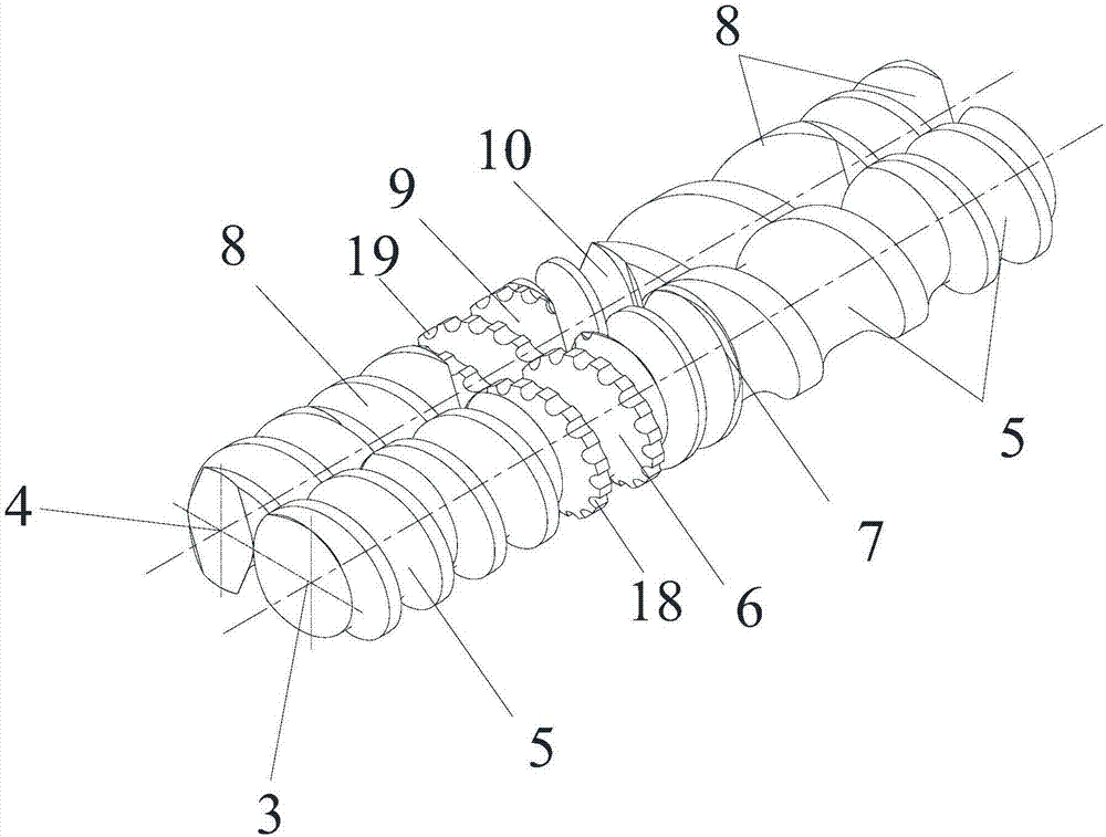
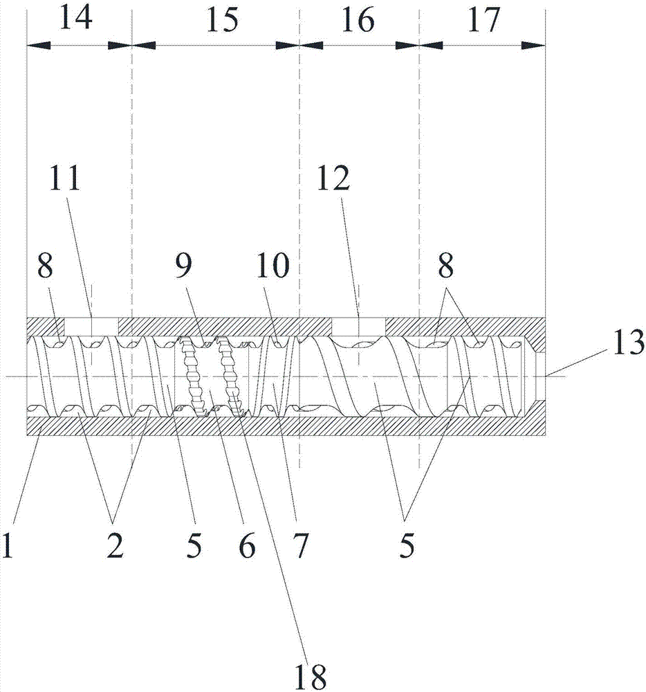
[0040] In this embodiment, a kind of strong stretching co-directional differential speed multi-screw extruder, such as figure 2 As shown, it includes a barrel 1 and a screw mechanism, the barrel 1 is provided with an inner cavity 2, and the screw mechanism is installed in the inner cavity, such as figure 1 As shown, the screw mechanism includes a first screw 3 and a second screw 4, the first screw and the second screw are engaged with each other, and the outermost edges of the first screw and the second screw are all tangent to the inner wall of the cavity; the first screw , The second screw and the inner cavity of the barrel form a flow channel; the first screw is connected in sequence by the first forward conveying element 5, the first mixing element 6, the first reverse conveying element 7 and the first forward conveying element 5 The second screw is composed of the second forward conveying element 8, the second kneading element 9, the second reverse conveying element 10 a...

Embodiment 2

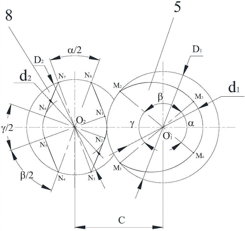
[0061] The present embodiment is a kind of strongly stretched co-directional differential multi-screw extruder, compared with embodiment 1, its difference is: as Figure 5 As shown, the outer diameter of the first screw is smaller than the outer diameter of the second screw, that is, the ratio between the outer diameter and the inner diameter of the second screw is 1.1 to 1.8, and the ratio between the outer diameter and the inner diameter of the first screw is 1.1 to 1.1. 4.5.

Embodiment 3

[0063] The present embodiment is a kind of strongly stretched co-directional differential multi-screw extruder, compared with embodiment 1, its difference is: as Image 6As shown, in the first screw, the first kneading element is a combined structure formed by connecting multiple first kneading blocks; in the second screw, the second kneading element is a combined structure formed by connecting multiple second kneading blocks. In addition to providing fully self-cleaning mixing with positive displacement conveying capacity and super large output, the mixing element of this structure also introduces a stronger tensile force field effect to provide more powerful dispersion and mixing capabilities.


PUM


Abstract

The invention discloses a strong-stretching same-direction differential multi-screw extruder and a machining method thereof. A screw mechanism of the extruder comprises a first screw and a second screw which are engaged, the first screw comprises a first forward conveying element, a first mixing element and a first reverse conveying element which are sequentially connected, the second screw comprises a second forward conveying element, a second mixing element and a second reverse conveying element which are sequentially connected, and the outer diameter of the first screw is not equal to the outer diameter of the second screw. The machining method of the extruder comprises the steps that after materials enter an inner cavity of a machine cylinder, and under the joint effect of axial forward displacement conveying force of the screw mechanism and friction force between the first screw and the second screw, material conveying is achieved; meanwhile, the speed difference and the diameter difference between the first screw and the second screw are used for generating the strong stretching effect, and the materials are sufficiently mixed, molten, mixed and plastified in the conveying process; the strong stretching effect generated by the different rotating speeds and diameters of the two screws is used for reinforcing the mixing and heat transfer process.

Description

technical field [0001] The invention relates to the technical field of multi-screw extruders, in particular to a multi-screw extruder with strong stretching co-direction and differential speed and a processing method thereof. Background technique [0002] The co-rotating twin-screw extruder with self-cleaning function is a widely used mixing processing equipment at present. This type of twin-screw extruder only provides disturbance in the meshing area to improve the mixing quality, and lacks a chaotic mixing trigger mechanism away from the meshing area. Moreover, the volume of the material in the left and right screw channels is the same, and the effect of the tensile force field is small. The main part of the volume lacks a structure that can effectively improve the mixing, which will lead to the inability to further improve the distribution mixing effect, and the lack of the tensile force field effect will lead to unsatisfactory dispersion mixing. In addition, most of the...

Claims


Application Information

Patent Timeline
IPC IPC(8): B29C47/40B29C47/60B29C47/74B29C48/74
CPCB29C48/402B29C48/535B29C48/57B29C48/575B29C48/59B29C48/745
Inventor 徐百平喻慧文王玫瑰
Owner GUANGDONG IND TECHN COLLEGE
Features
  • R&D
  • Intellectual Property
  • Life Sciences
  • Materials
  • Tech Scout
  • Unparalleled Data Quality
  • Higher Quality Content
  • 60% Fewer Hallucinations
Learn More