
Non-equal phase front correction method of material complex permittivity quasi-optical cavity method wideband test

A technology of complex permittivity and optical cavity, which can be used in dielectric performance measurement, measurement device, measurement of electrical variables, etc., can solve problems such as implementation difficulties, large errors, and uneven cavity analysis, and achieve the effect of improving test accuracy.

Inactive Publication Date: 2017-09-08
UNIV OF ELECTRONICS SCI & TECH OF CHINA
View PDF3 Cites 8 Cited by
  • Summary
  • Abstract
  • Description
  • Claims
  • Application Information

AI Technical Summary

Problems solved by technology

Due to the limitations of the above conditions, in order to reduce the broadband test error, it is necessary to provide multiple samples of the same material with different thicknesses for different frequency ranges, which is difficult to achieve, and direct broadband testing with a single sample will lead to large errors. It makes it difficult to use the quasi-optical cavity for accurate broadband testing
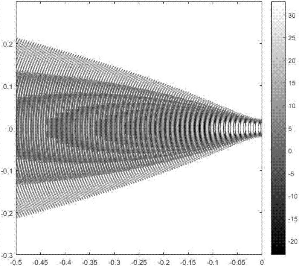
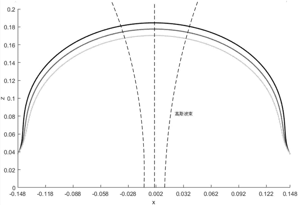
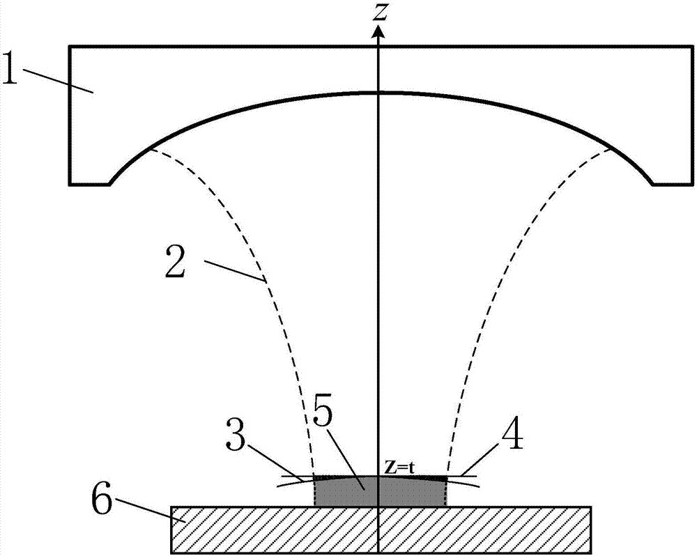
[0008] In the book "Theory and Application of Electromagnetic Dielectric Resonators" edited by Li Ying et al., in the chapter "Open Resonator", the theoretical derivation of the medium-loaded near-confocal cavity (also known as the double concave cavity) is made, considering the dielectric sheet The surface is plane, and the equiphase plane of the Gaussian beam here is non-planar, which leads to the error caused by the mismatch. On the correction of non-equal phase planes in the broadband test of electric constant quasi-cavity method

Method used


Image

  • Non-equal phase front correction method of material complex permittivity quasi-optical cavity method wideband test
  • Non-equal phase front correction method of material complex permittivity quasi-optical cavity method wideband test
  • Non-equal phase front correction method of material complex permittivity quasi-optical cavity method wideband test

Examples


Embodiment Construction

[0051] Embodiments of the present invention are described below through specific examples, and those skilled in the art can easily understand other advantages and effects of the present invention from the content disclosed in this specification. The present invention can also be implemented or applied through other different specific implementation modes, and various modifications or changes can be made to the details in this specification based on different viewpoints and applications without departing from the spirit of the present invention.

[0052] A method for correcting non-equal phase planes in broadband testing by quasi-optical cavity method for complex permittivity of materials, comprising the following steps:

[0053] (1) The phase distribution of the Gaussian beam in the collimated optical cavity is analyzed by beam theory;

[0054] The phase expression of the Gaussian beam can be obtained from the beam theory and the wave equation:

[0055]

[0056] where k is t...


PUM


Abstract

The present invention provides a non-equal phase front correction method of a material complex permittivity quasi-optical cavity method wideband test. The sample wideband complex permittivity accuracy test can be realized. Gaussian beam electromagnetic field phase distribution in a quasi-optical cavity is analyzed, and an actual phase distribution function at the upper surface of a sample is obtained according to the upper surface of a sample to be tested, namely the matching relation of the air and a waist radius at a medium area interface. The perturbation theory is employed to solve the stored energy at the gap of the surface plane and the wavefront spherical surface so as to obtain frequency shift caused by phase mismatching of the sample surface and the wavefront. The non-equal phase surface at the upper surface of the sample is corrected through combination of a preset format; the influence of non-equal phase surface errors caused by thickness of the sample in the quasi-optical cavity method wideband test is corrected, the wideband test of the material complex permittivity through adoption of the quasi-optical cavity method can be effectively performed, and the precision of the multimode wideband test of the quasi-optical cavity method can be improved.

Description

technical field [0001] The invention belongs to the technical field of dielectric material testing, and in particular relates to a microwave and millimeter wave frequency band quasi-optical resonant cavity method and a broadband testing technology for the complex dielectric constant of dielectric materials. Background technique [0002] In the technical field of microwave dielectric material complex permittivity measurement, the resonant cavity method has been popularized and applied due to its high sensitivity and high measurement accuracy. Generally, closed resonators are widely used in the centimeter band when using the resonance method for microwave measurements. However, in the high microwave frequency range, the use of resonant cavities will encounter difficulties. First, since the size of the resonant cavity is proportional to the resonant wavelength, when the operating frequency increases, the size of the resonant cavity will decrease accordingly, and the Q value of...

Claims


Application Information

Patent Timeline
IPC IPC(8): G01R27/26
CPCG01R27/2682
Inventor 李恩郭高凤张云鹏张俊武何凤梅邹翘余承勇高冲高勇李亚峰
Owner UNIV OF ELECTRONICS SCI & TECH OF CHINA
Learn More