Structural light microscopic imaging system based on line scanning time-space focusing

A microscopic imaging and line scanning technology, applied in the field of computational photography, can solve the problems of reduced image quality and contrast, slow adjustment speed, and inability to generate fringes of different frequencies, so as to improve resolution and contrast, and reduce out-of-focus excitation. , adjust the fast and flexible effect

Inactive Publication Date: 2017-09-08
TSINGHUA UNIV
View PDF10 Cites 38 Cited by
  • Summary
  • Abstract
  • Description
  • Claims
  • Application Information

AI Technical Summary

Problems solved by technology

Line-scan spatio-temporal focusing improves the axial resolution and signal-to-noise ratio on the basis of ensuring the imaging speed, but it still has the problem of image quality and contrast degradation for imaging in strong scattering media
It is particularly important that the existing structured light microscope produces sinusoidal fringes through grating interference. A grating with a linear density only corresponds to fringes with a fixed spatial frequency, and changing the phase requires precise displacement of the grating, so the adjustment speed is slow and cannot be adjusted according to Need to flexibly generate stripes of different frequencies

Method used


Image

  • Structural light microscopic imaging system based on line scanning time-space focusing
  • Structural light microscopic imaging system based on line scanning time-space focusing
  • Structural light microscopic imaging system based on line scanning time-space focusing

Examples


Embodiment Construction

[0024] Embodiments of the present invention are described in detail below, examples of which are shown in the drawings, wherein the same or similar reference numerals designate the same or similar elements or elements having the same or similar functions throughout. The embodiments described below by referring to the figures are exemplary and are intended to explain the present invention and should not be construed as limiting the present invention.

[0025] A structured light microscopy imaging system based on line-scan spatio-temporal focusing according to an embodiment of the present invention will be described below with reference to the accompanying drawings.

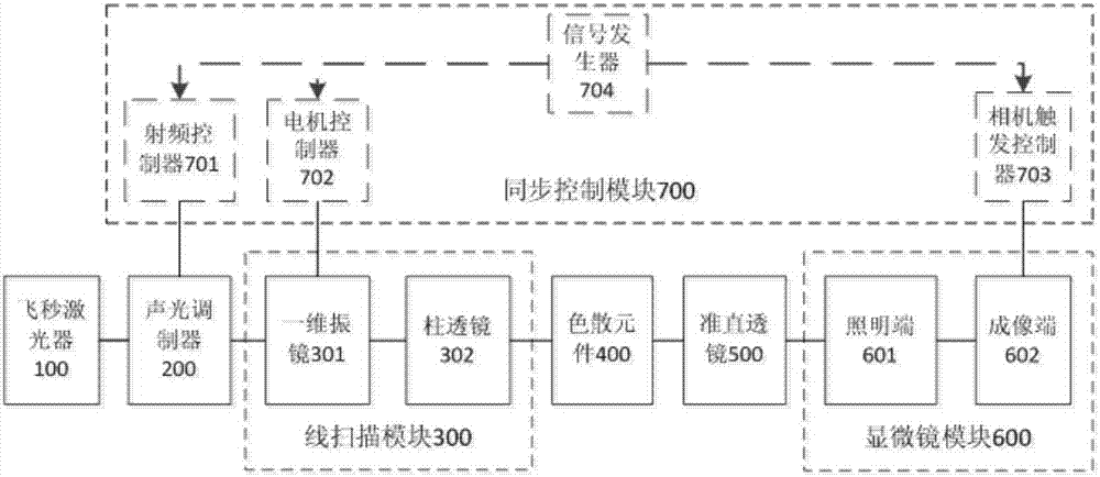
[0026] figure 1 It is a structural schematic diagram of a structured light microscopy imaging system based on line-scan spatio-temporal focusing according to an embodiment of the present invention.

[0027] Such as figure 1 As shown, the structured light microscopy imaging system based on line-scan spatio-tempora...


PUM


Abstract

The invention discloses a structural light microscopic imaging system based on line scanning time-space focusing. The system comprises the components of a femto second laser device; an acousto-optical modulator which is used for periodically modulating light source strength according to a sine function; a line scanning module which is used for scanning in a linear focusing light spot direction and a vertical linear light spot function; a dispersion element which is used for generating a spatial chirp; a collimating lens which is used for focusing different frequency components after grating dispersion to a parallel transmission direction; a microscope module; and a synchronous control module which is used for performing synchronous controlling on the acousto-optical modulator, the line scanning module and the microscope module, thereby obtaining a reconstructed image. According to the structural light microscopic imaging system, the reconstructed image can be obtained through strength-modulated line scanning structural light illumination in a line scanning time-space focused scanning mode and strength change of synchronously modulated excited light, thereby improving resolution and contrast in line scanning time-space focusing and reducing excitation outside a focal plane caused by medium scattering.

Description

technical field [0001] The invention relates to the technical field of computational imaging, in particular to a structured light microscopic imaging system based on line-scanning spatio-temporal focusing. Background technique [0002] Two-photon fluorescence microscopy is a fluorescence microscopy technique that uses the nonlinear effect of fluorescence excitation for imaging. It generates short-wavelength fluorescence through long-wavelength excitation light, which has the advantages of deep penetration depth and almost no excitation in out-of-focus areas. [0003] Among them, the traditional two-photon fluorescence microscope works in a point-scanning mode, and its scanning speed decreases with the increase of the field of view, so it is difficult to achieve fast imaging in a large field of view. Space-time focusing technology is a two-photon microscopy technology based on time-domain compression. It disperses the time-chirped femtosecond laser to obtain a spatially chirp...

Claims


Application Information

Patent Timeline
Patent Type & Authority Applications(China)
IPC IPC(8): G02B21/36G02B21/00
CPCG02B21/0032G02B21/0048G02B21/361G02B21/0076G02B21/0084G02B21/16G01N21/6458G02B21/06G02B27/0068G02B21/241
Inventor 戴琼海李子薇
Owner TSINGHUA UNIV
Why Eureka
Try Eureka