Buck converter with connection time being controlled

An on-time, converter technology, applied in output power conversion devices, DC power input conversion to DC power output, instruments, etc., can solve problems to be optimized, etc., achieve small transient response overshoot, fast transient Response speed, the effect of ensuring frequency stability

Active Publication Date: 2017-09-08
UNIV OF ELECTRONICS SCI & TECH OF CHINA
View PDF3 Cites 17 Cited by
  • Summary
  • Abstract
  • Description
  • Claims
  • Application Information

AI Technical Summary

Problems solved by technology

Therefore, this type of buck converter has a duty cycle limitation, and its output voltage V OUT Overshoot and dynamic voltage scaling DVS response to be optimized

Method used


Image

  • Buck converter with connection time being controlled
  • Buck converter with connection time being controlled
  • Buck converter with connection time being controlled

Examples


Embodiment Construction

[0026] Below in conjunction with accompanying drawing, describe technical scheme of the present invention in detail:

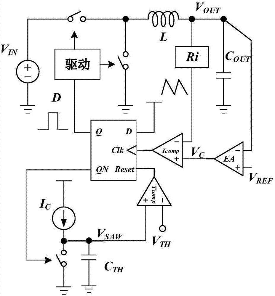
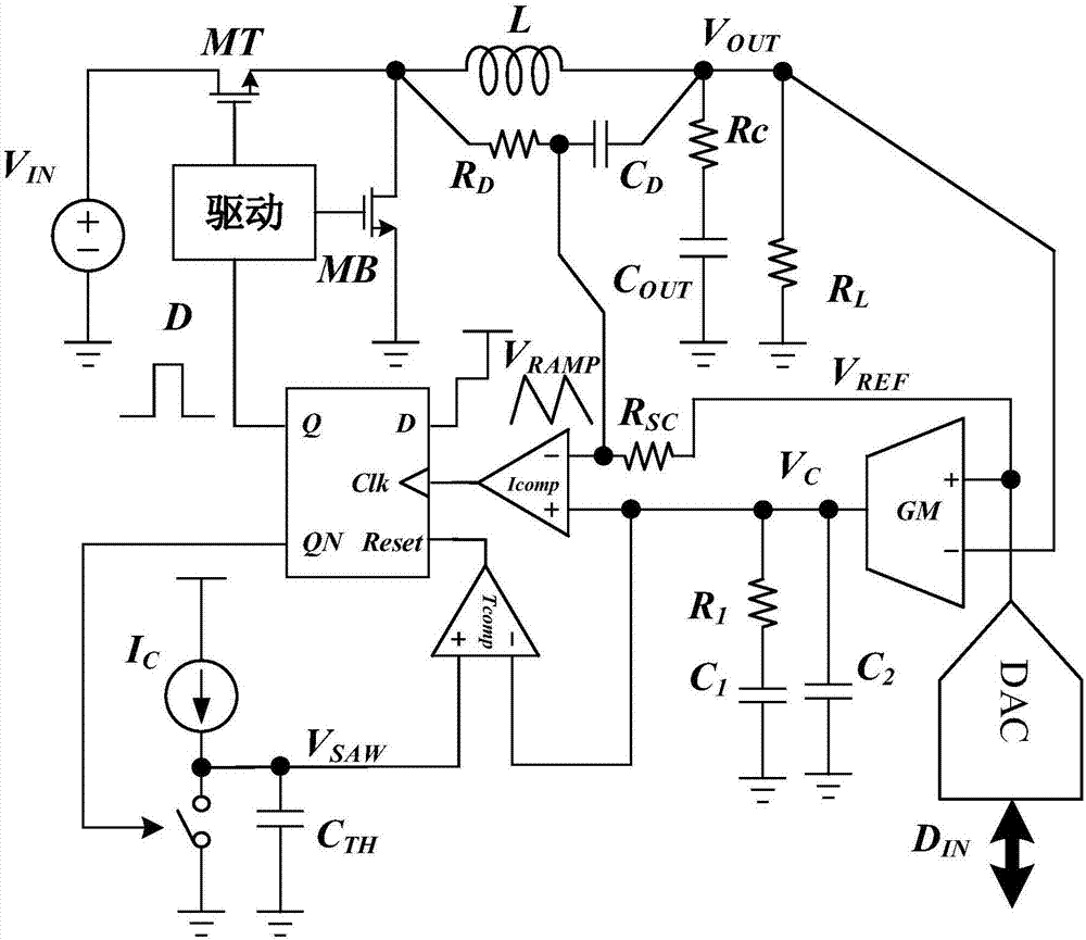
[0027] Such as image 3 Shown is a schematic structural diagram of a step-down converter system with a controlled turn-on time proposed by the present invention, including an upper power tube MT, a lower power tube MB, a drive circuit, an inductor L, and an output capacitor C OUT , D flip-flop, current source IC , timing capacitor C TH , switch circuit, first comparator I comp And the second comparator Tcomp, the drain of the upper power transistor MT is connected to the input voltage V IN , whose source is connected to the drain of the power tube MB and passes through the inductor L and the output capacitor C OUT After the series structure of the series structure is grounded, its series point is used as the output end of the step-down converter; the source of the lower power tube MB is grounded; the switch circuit and the timing capacitor C TH Parallel co...


PUM


Abstract

The invention discloses a buck converter with the connection time being controlled, and relates to electronic circuit technologies. Through a digital-to-analog converter, a reference voltage is generated, a voltage signal of a sampled inductive current is superposed to obtain a ramp signal VRAMP, after the ramp signal VRAMP is compared with an output voltage VC of a transconductance amplifier, start-up or switch-off of an upper-lower power tube is controlled through a D flip flop, when the ramp signal VRAMP is lowered to a valley current which is determined by the voltage VC of the transconductance amplifier, a first comparator Icomp outputs a logic level signal and makes an upper power tube MT be connected through the D flip flop and a lower power tube MB be switched off, thus the inductive current is increased, and the output voltage is raised, wherein the connection time of the upper power tube MT is jointly determined by a timing capacitor CTH and an output voltage signal VC of the transconductance amplifier GM. According to the buck converter with the connection time being controlled, the buck converter has smaller transient response overshoot impulse and higher transient response speed, and is particularly applicable to application occasions like an FPGA and a CPU which have high transient requirements on a power source.

Description

technical field [0001] The invention relates to electronic circuit technology, in particular to a Buck converter whose conduction time is controlled by a transconductance amplifier signal (Variable on Time, VOT). Background technique [0002] Buck converter is a commonly used topology in switching power supply, which can realize level conversion from DC voltage to DC voltage. Among them, the buck converter with constant on-time control (Constant on Time, COT) is widely used in various power systems due to its fast transient response speed and high light-load efficiency. [0003] The system structure of constant on-time buck converter is as figure 1 As shown, the control principle is as follows: When the output voltage VOUT is higher than the reference voltage V REF When it is high, the error amplifier EA outputs a voltage signal V C lower, the first comparator Icomp compares the inductor current sampling signal with the error amplifier EA output voltage signal V C , when...

Claims


Application Information

Patent Timeline
Patent Type & Authority Applications(China)
IPC IPC(8): H02M3/158
CPCH02M3/158
Inventor 甄少伟周孙泽杨明宇曾鹏灏陈佳伟周万礼罗萍张波
Owner UNIV OF ELECTRONICS SCI & TECH OF CHINA
Why Eureka
Try Eureka