Duty ratio correcting circuit

A duty cycle and circuit technology, applied in the direction of electrical components, electric pulse generation, pulse generation, etc., can solve problems such as long stabilization time, jitter, circuit complexity, etc., and achieve the effect of avoiding loop stability and loop compensation

Pending Publication Date: 2017-09-08
CHENGDU ANALOG CIRCUIT TECH INC
View PDF11 Cites 5 Cited by
  • Summary
  • Abstract
  • Description
  • Claims
  • Application Information

AI Technical Summary

Problems solved by technology

[0004] When the signal frequency is relatively low, the filter capacitor of the DC level signal is usually large and has a small ripple, which will introduce jitter; and the error amplifier is always misaligned during the production process, which will cause the duty cycle The ratio cannot meet the requirements, and the circuit is more complicated, requiring a longer stabilization time

Method used


Image

  • Duty ratio correcting circuit
  • Duty ratio correcting circuit
  • Duty ratio correcting circuit

Examples


Embodiment Construction

[0021] The technical solution of the present invention will be further described in detail below in conjunction with the accompanying drawings, but the protection scope of the present invention is not limited to the following description.

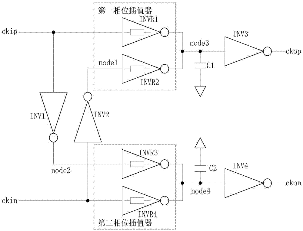
[0022] Such as figure 1 As shown, the duty ratio correction circuit of the present invention includes a first signal input terminal ckip, a second signal input terminal ckin, a first inverter INV1 connected to the first signal input terminal ckip, a first phase interpolator, and a second The second inverter INV2 connected to the signal input terminal ckin and the second phase interpolator, the first capacitor C1 connected to the first phase interpolator and the third inverter INV3, the second capacitor connected to the second phase interpolator C2, the fourth inverter INV4, the first signal output terminal ckop connected to the third inverter INV3, and the second signal output terminal ckon connected to the fourth inverter INV4.

[0023] I...


PUM


Abstract

The present invention discloses a duty ratio correcting circuit. The circuit comprises a first signal input end, a second signal input end, a first phase inverter, a first phase interpolator, a second phase inverter, a second phase interpolator, a first capacitor, a third phase inverter, a second capacitor, a fourth phase inverter, a first signal output end and a second signal output end. The input signal of the second signal input end is reverse in phase to the input signal of the first signal input end. The first phase inverter is connected with the first signal input end. The first phase interpolator is connected with the first signal input end. The second phase inverter is connected with the second signal input end. The second phase interpolator is connected with the second signal input end. The first capacitor is connected with the first phase interpolator. The third phase inverter is connected with the first phase interpolator. The second capacitor is connected with the second phase interpolator. The fourth phase inverter is connected with the second phase interpolator. The first signal output end is connected with the third phase inverter. The second signal output end is connected with the fourth phase inverter. The phases of higher harmonics are regulated by the first phase interpolator and the second phase interpolator and amplified to a full swing by the third phase inverter and the fourth phase inverter. According to the technical scheme of the invention, the problems of loop stability and loop compensation can be avoided.

Description

technical field [0001] The invention relates to the field of integrated circuits, in particular to a duty ratio correction circuit for correcting the duty ratio of an output signal of a differential oscillator. Background technique [0002] In the design of the oscillator, the output signal of the oscillator has different duty ratios at different frequencies. When the duty ratio of the output signal is strictly required, a duty ratio correction circuit is usually set at the output end of the oscillator. [0003] In the existing duty cycle correction circuit, the output signal of the oscillator is often filtered first to obtain a DC level signal, and then the error is amplified between the DC level signal and 1 / 2 of the power supply voltage to obtain a control signal to adjust charging or The equivalent impedance of the discharge, and then adjust the rising or falling time of the signal, thereby adjusting the duty cycle. [0004] When the signal frequency is relatively low, ...

Claims


Application Information

Patent Timeline
Patent Type & Authority Applications(China)
IPC IPC(8): H03K3/017
CPCH03K3/017
Inventor 何天长连颖
Owner CHENGDU ANALOG CIRCUIT TECH INC
Why Eureka
Try Eureka