Polisher for industrial machinery

A technology for industrial machinery and grinding machines, applied in grinding machines, manufacturing tools, grinding racks, etc., can solve problems such as inability to eliminate noise, inability to adjust the height of grinding objects, etc., to achieve the effect of noise reduction and convenient movement

Inactive Publication Date: 2017-09-12
SUZHOU ZHIRUI PHOTOELECTRIC MATERIAL TECH CO LTD
View PDF0 Cites 6 Cited by
  • Summary
  • Abstract
  • Description
  • Claims
  • Application Information

AI Technical Summary

Problems solved by technology

[0003] The invention provides a grinding machine for industrial machinery, which can effectively solve the defect

Method used


Image

  • Polisher for industrial machinery
  • Polisher for industrial machinery
  • Polisher for industrial machinery

Examples


Embodiment 1

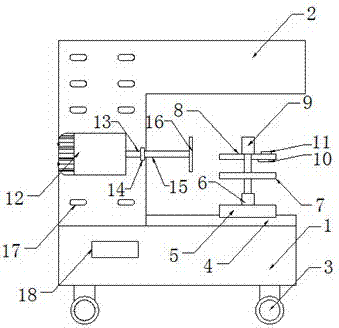
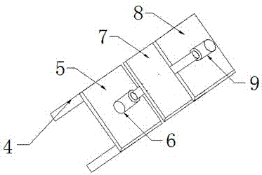
[0017] Such as Figure 1-3 As shown, a grinding machine for industrial machinery of the present invention includes a base 1 and a workbench 2, the bottom end of the base 1 is equipped with a roller 3, one side of the base 1 is provided with a control panel 18, and the top of the base 1 is fixedly installed with a sliding wheel. Rail 4, the top of the base 1 is fixedly connected to the bottom of the workbench 2, the slide rail 4 is slidably connected to the bottom plate 5, the top of the bottom plate 5 is fixedly connected to the bottom of the first hydraulic cylinder 6, and the first hydraulic cylinder 6 is connected through the hydraulic rod It is connected with the lower splint 7, the lower splint 7 is connected with the upper splint 8 through a hydraulic rod, the second hydraulic cylinder 9 is arranged on the upper splint 8, the first hydraulic cylinder 6 and the second hydraulic cylinder 9 are electrically connected with the control panel 18, and the upper splint A pressur...


PUM


Abstract

The invention discloses a polisher for industrial machinery. The polisher comprises a base and a worktable; rollers are arranged on the bottom end of the base; a control panel is arranged on one side of the base; a slide rail is fixedly arranged on the top end of the base; the top end of the base is fixedly connected to the bottom end of the worktable; the slide rail is connected to a bottom plate in a slidable manner; the top end of the bottom plate is fixedly connected with the bottom end of a first hydraulic cylinder; the first hydraulic cylinder is connected with a lower clamping plate through a hydraulic rod; the lower clamping plate is connected with the upper clamping plate through the hydraulic rod; a second hydraulic cylinder is arranged on the upper clamping plate; and a pressure sensor is arranged on the bottom end of the first hydraulic cylinder. According to the polisher, the rollers are arranged on the base, so that the polisher can be moved more conveniently; the polishing height of a polished object can be adjusted by the first hydraulic cylinder; the polished object can be tightly clamped by the second hydraulic cylinder, so that the phenomenon that the polished object sways to affect machining quality is avoided; and the pressure sensor senses pressure to the polished object applied by the upper clamping plate and transmits a signal to a display, so that the phenomenon that the pressure is overlarge to damage the polished object is prevented.

Description

technical field [0001] The invention relates to a grinder, in particular to a grinder for industrial machinery, belonging to the technical field of industrial machinery. Background technique [0002] Grinding machines are widely used in finishing and surface polishing of workpieces. Existing grinding machines include fixed grinding machines and mobile grinding machines. The fixed grinding machine is fixed on the base, and then the workpiece is placed on the grinding wheel for grinding. However, the current The grinding machine cannot adjust the distance between the grinding object and the grinding knife, and cannot feel the pressure generated by the splint on the grinding object, which is easy to damage the grinding object, and cannot reduce the noise generated during the grinding process of the grinding machine. Contents of the invention [0003] The invention provides a grinding machine for industrial machinery, which can effectively solve the defects that the traditiona...

Claims


Application Information

Patent Timeline
IPC IPC(8): B24B27/02B24B41/02B24B41/06B24B55/00B24B49/16B24B47/08
CPCB24B27/02B24B41/02B24B41/06B24B47/08B24B49/16B24B55/00
Inventor 王永飞
Owner SUZHOU ZHIRUI PHOTOELECTRIC MATERIAL TECH CO LTD
Why Eureka
Try Eureka