Electric horn adopting diode to carry out absorption of induced electromotive force on inductance coil and control method
A technology of induced electromotive force and inductive coil, which is applied in the direction of sensors, electrical components, transducer circuits, etc., can solve the problems of low reliability, high cost, and high drain voltage, and achieve good reliability, improved life, and no secondary The effect of breakdown
- Summary
- Abstract
- Description
- Claims
- Application Information
AI Technical Summary
Problems solved by technology
Method used
Image

Examples
Embodiment 1
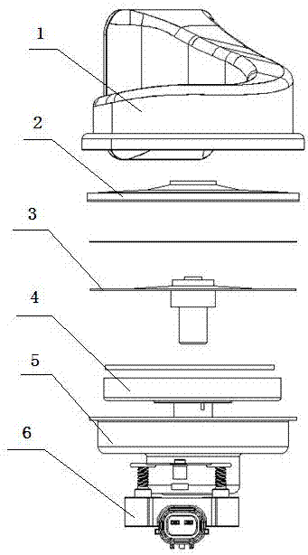
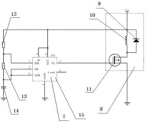
[0017] An electric horn in which a diode is used as an induction coil to absorb electromotive force, which is composed of: a terminal 6 which is fixedly connected to the coil frame 4 through a housing 5, and the terminal is connected to the wiring harness of the car body, so The housing and the diaphragm 3 are fixedly connected by a gland 2, a plastic shell 1 is installed on the gland, a circuit board is installed on the coil frame, and the circuit board includes a power circuit 8, a control circuit 7. The power circuit is electrically connected to the control circuit. The power circuit is composed of a switch 11, an inductor 10, and a diode 9. The diode is connected in parallel with the inductor, and the inductor The upper end of the inductor is connected to Vcc, the lower end of the inductor is connected to the switch, and the cathode of the diode is connected to the upper end of the inductor.
Embodiment 2
[0019] According to the diode described in embodiment 1 as an electric horn with induction electromotive force absorption, the control circuit includes a 555 chip 15, a resistor A, part number: 12, a resistor B, part number: 13 and a capacitor 14. The Vo pin on the 555 chip is connected to the switch, and the Vcc terminal of the power circuit is respectively connected to the resistor A, the Vcc pin on the 555 chip and the R lead on the 555 chip. The resistor A is connected to the resistor B and the DIS pin on the 555 chip, and the resistor B is connected to the TR pin on the 555 chip and the 555 chip. The THR pin on the chip is connected to one end of the capacitor, and the other end of the capacitor and the GND pin on the 555 chip and the switch are grounded respectively.
Embodiment 3
[0021] A method for controlling an electric horn using a diode as an induction coil to absorb electromotive force. The method includes the following steps: after power is turned on, the 555 chip generates a fixed frequency square wave drive signal to control the on and off of the switch. When it is turned on, there is current flow Pass the inductance coil to attract the diaphragm. When it is disconnected, no current flows through the inductance coil and the diaphragm is released. This makes a sound after reciprocating vibration. When the switch is off, the inductance coil generates an induced electromotive force, and the diode will be turned on instantly. Clamp the induced electromotive force to a low voltage to protect the switch.
PUM
 Abstract
Description
Claims
Application Information
 - R&D
- Intellectual Property
- Life Sciences
- Materials
- Tech Scout
- Unparalleled Data Quality
- Higher Quality Content
- 60% Fewer Hallucinations
Browse by: Latest US Patents, China's latest patents, Technical Efficacy Thesaurus, Application Domain, Technology Topic, Popular Technical Reports.
© 2025 PatSnap. All rights reserved.Legal|Privacy policy|Modern Slavery Act Transparency Statement|Sitemap|About US| Contact US: help@patsnap.com