Digital pressure gauge for lumbar puncture with controllable cerebrospinal fluid

A cerebrospinal fluid and manometry technology, which is applied in the field of clinical medicine and medical devices, can solve problems such as reducing the incidence of brain herniation, and achieve the effects of reducing the incidence of brain herniation, contributing to disease assessment, and stable and reliable performance.

Active Publication Date: 2017-09-15
THE FIRST HOSPITAL OF CHINA MEDICIAL UNIV
View PDF10 Cites 9 Cited by
  • Summary
  • Abstract
  • Description
  • Claims
  • Application Information

AI Technical Summary

Problems solved by technology

[0006] The purpose of the present invention is to provide a digital lumbar puncture manometer with controllable flow rate and flow of cerebrospinal fluid, which overcomes the deficiencies of the prior art, applies digital pressure detection technology to lumbar puncture manometer, and can be retained without removing the manometer tube Cerebrospinal fluid, and the flow rate of cerebrospinal fluid can be adjusted according to the pressure value to ensure the safety of lumbar puncture operation; it can display the intracranial pressure value after lumbar puncture, which is of guiding significance for patients' resting position and medication after lumbar puncture; when the pressure of cerebrospinal fluid of patients is too high , can read the intracranial pressure value in a safe situation, reduce the incidence of brain herniation, and help the disease assessment

Method used


Image

  • Digital pressure gauge for lumbar puncture with controllable cerebrospinal fluid
  • Digital pressure gauge for lumbar puncture with controllable cerebrospinal fluid

Examples


Embodiment Construction

[0028] The specific embodiments of the present invention will be further described below in conjunction with the accompanying drawings.

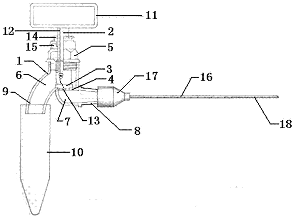
[0029] See figure 1 , figure 2 , is a schematic structural diagram of an embodiment of a digital lumbar puncture manometer with controllable cerebrospinal fluid flow in the present invention. The structure includes an instrument housing 1, a valve stem 2, a valve head 3, a valve seat 4 and a nut sleeve 5, and the inside of the instrument housing 1 is partially narrowed to form Valve seat 4, the valve seat 4 divides the inner cavity of the instrument housing into a cerebrospinal fluid drainage chamber 6 and a pressure detection chamber 7, the valve head 3 is located at the bottom of the valve stem 2, the shape of the valve head 3 matches the valve seat 4, when the valve head 3 When it fits tightly with the valve seat 4 (the valve is closed), the channel between the cerebrospinal fluid drainage chamber 6 and the pressure detection chamber 7 ...


PUM


Abstract

The invention relates to the field of medical instruments, in particular to a digital pressure gauge for lumbar puncture with controllable cerebrospinal fluid. The gauge comprises a lumbar spinal needle connecting end, a cerebrospinal fluid connecting end, a pressure sensor and a numeric display meter and is characterized in that the interior of a housing of the gauge is partially narrowed to form a valve seat; the valve seat divides an inner cavity of the housing into a cerebrospinal fluid drainage cavity and a pressure detection cavity; when a valve head is closely attached to the valve seat, a channel between the cerebrospinal fluid drainage cavity and the pressure detection cavity is blocked; when the valve head is away from the valve seat, the cerebrospinal fluid drainage cavity communicates with the pressure detection cavity; and the lumbar spinal needle connecting end and the cerebrospinal fluid connecting end are arranged; and the cerebrospinal fluid connecting end is a section of 90-degree bent pipe. Compared with the prior art, the digital pressure gauge for lumbar puncture with the controllable cerebrospinal fluid has the following advantages: pressure value can be read at any time before collection of cerebrospinal fluid and during collection of cerebrospinal fluid; intracranial pressure valve after lumbar puncture can be displayed; and the digital pressure gauge can play an important role in guiding the positions and medicine use for a patient who takes a rest after lumbar puncture.

Description

technical field [0001] The invention relates to the field of clinical medicine and medical equipment, in particular to a digital lumbar puncture manometer with controllable cerebrospinal fluid velocity and flow, which can be widely used in neurology, surgery, etc. to monitor the intracranial pressure of patients and perform lumbar puncture When taking cerebrospinal fluid. Background technique [0002] Lumbar puncture is a diagnostic operation often performed in neurology and surgery. It is mainly used for the identification of diseases such as encephalitis, demyelinating disease, paraneoplastic syndrome, and subarachnoid hemorrhage. Important value, any imaging examination can not replace the importance of lumbar puncture. At present, the main steps of lumbar puncture are: 1) The patient lies supine with the pillow removed, bends the neck and hips, hugs the knees with both hands, and keeps the shoulders perpendicular to the bed surface; 2) Select the gap between waist 3-4 o...

Claims


Application Information

Patent Timeline
Patent Type & Authority Applications(China)
IPC IPC(8): A61B17/34A61B5/03A61B10/00A61M1/00
CPCA61M1/0023A61B5/031A61B5/6849A61B10/0045A61B17/34A61B17/3494A61B2010/0077A61M2202/0464A61M1/743A61M2202/0014
Inventor 赵传胜于航赵岚青李进伟王翔梁怡凡张秀春孙叶飞
Owner THE FIRST HOSPITAL OF CHINA MEDICIAL UNIV
Why Eureka
Try Eureka