

Aeration unit, aeration device, aeration float and aeration method
An aeration device and aeration technology, applied in water aeration, chemical instruments and methods, degassed water/sewage treatment, etc., can solve the problems that floating bodies have no aeration function, are not suitable for biological survival, and have low oxygen supply efficiency , to achieve the effect of facilitating mass production, improving oxygen supply efficiency, and simple structure
- Summary
- Abstract
- Description
- Claims
- Application Information
AI Technical Summary
Problems solved by technology
Method used
Image

Examples
no. 1 approach
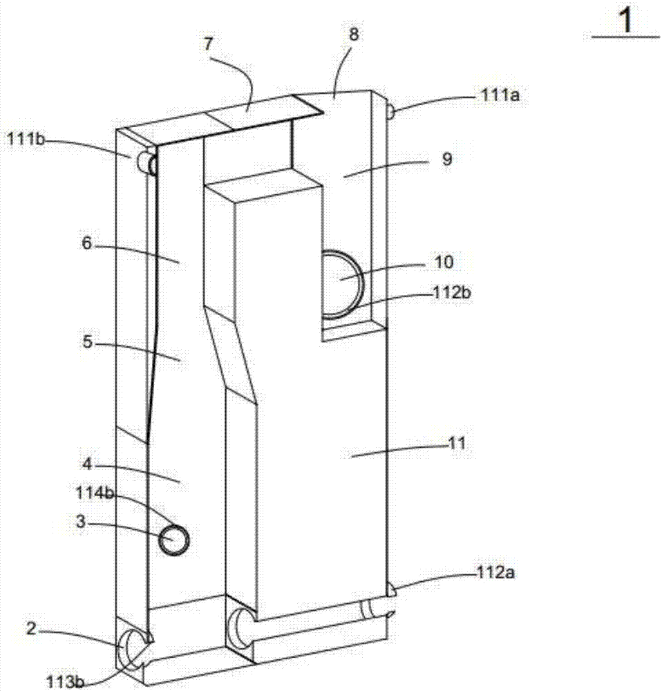
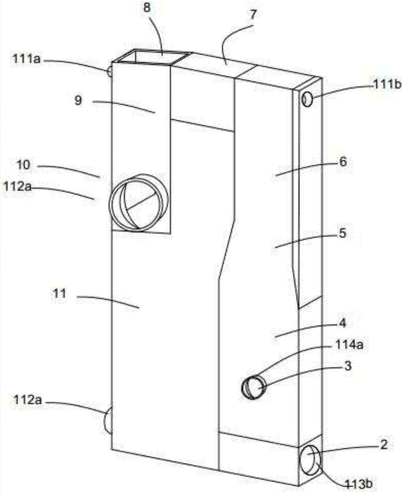
[0037] In order to illustrate Example 1 more clearly, in figure 1 with figure 2 Among them, the side of the outer surface with the air inlet 3 and the water outlet 10 is called the first outer surface side, and the outer surface side opposite to the first outer surface side is called the second outer surface side. And the left and right sides of the outer surface provided with the air inlet 3 and the water outlet 10 are the third outer surface side and the fourth outer surface side. It should be noted that these limitations are for illustration only.
[0038] The aeration unit 1 of this embodiment is an aeration unit installed in water, specifically, the aeration unit 1 may be installed in a water area with a water depth of, for example, 10-50 cm. The aeration unit 1 has a water-air passage inside, integrates the floating body and the aeration function, and is especially suitable for water purification and water pollution prevention and control in aquaculture and river chan...
no. 2 approach
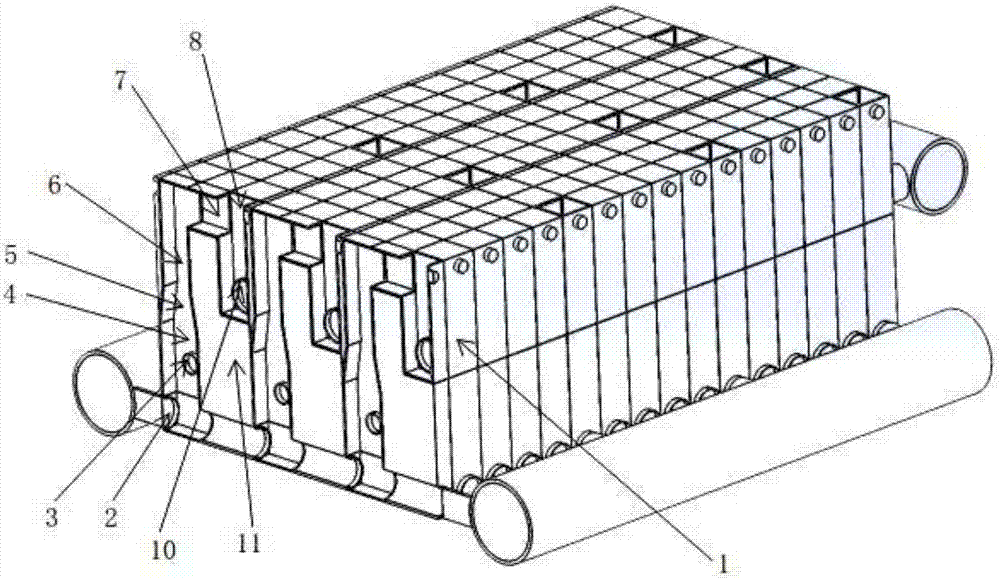
[0041] The aeration unit in this embodiment can be used alone, or two or more aeration units can be combined and connected together as an aeration unit. The aeration unit of the present invention belongs to shallow water aeration and has low power requirements, that is, the area of solar panels required for power is smaller when the device is installed, which is beneficial to the miniaturization of the device. In addition, under the same power, the amount of treated water is large, which has an energy-saving effect. Such as image 3 , Figure 7 with Figure 11 As shown, a plurality of aeration units or a plurality of combined aeration units are connected to form an aeration device. Aeration devices can be used in lakes, aquaculture farms, sewage treatment plants, etc., for example, in such as Figure 4 In the shown ecological floating island, the aeration unit is used to aerate the water at a water depth of, for example, 10-50 cm, so that convection can be formed between...
Embodiment 2
[0047] In order to illustrate Example 2 more clearly, in Figure 5 with Image 6 Among them, the side of the outer surface with the air inlet 3 and the water inlet 2 is called the first outer surface side, and the outer surface side opposite to the first outer surface side is called the second outer surface side. In addition, in this embodiment, the same or components as those of Example 1 and Example 2 are denoted by the same reference numerals.
[0048] The difference from Example 1 is that in the aeration unit 1 of this embodiment, as image 3 with Figure 4 As shown, the structure of the aeration unit 1 is symmetrical with respect to the left and right directions of the paper, and the water inlet 2 and the air inlet 3 are arranged on the outer surface of the lower part of the aeration unit 1 in a manner parallel to the central axis, so that the gas and water flow The output direction is bidirectional, that is, there are two output paths. Different from the constricted ...
PUM
 Abstract
Description
Claims
Application Information