Efficient oil removal device for rare earth material liquid

A rare earth material liquid and high-efficiency technology, which is applied in the direction of improving process efficiency, can solve the problems of rare earth material liquid high efficiency and oil removal, and achieve high oil removal efficiency, safe and reliable performance, and stable operation.

Active Publication Date: 2017-09-15
XUZHOU NANFANG YONGCI MATERIAL
View PDF5 Cites 8 Cited by
  • Summary
  • Abstract
  • Description
  • Claims
  • Application Information

AI Technical Summary

Problems solved by technology

[0005] In order to overcome the disadvantage that the existing oil removal device for rare earth material liquid usually adopts the traditional structure and cannot efficiently remove oil for rare earth material liquid, the technical problem to be solved by the present invention is to provide a rare earth material liquid High-efficiency degreasing device for liquid

Method used


Image

  • Efficient oil removal device for rare earth material liquid
  • Efficient oil removal device for rare earth material liquid
  • Efficient oil removal device for rare earth material liquid

Examples


Embodiment 1

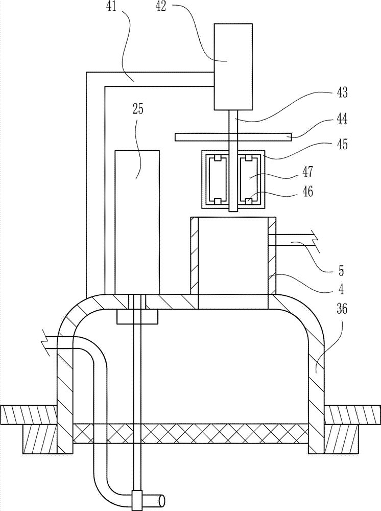
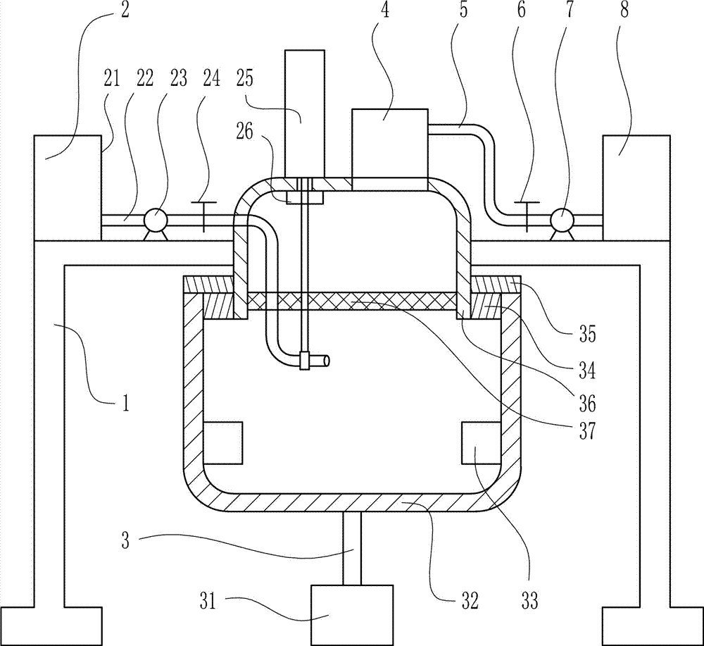
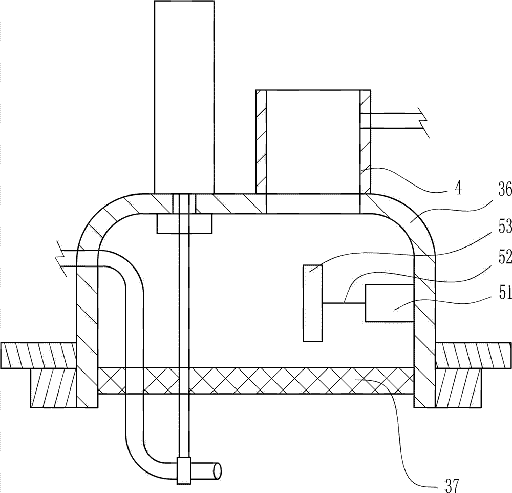
[0027] A high-efficiency oil removal device for rare earth feed liquid, such as Figure 1-3 As shown, it includes a large L-shaped support 1, a feed liquid conveying device 2, a rotating device 3, a jacking pipe 4, a connecting pipe 5, a valve I6, a high-pressure pump I7 and a receiving liquid tank 8; the large L-shaped support 1 is left-right symmetrical The material and liquid conveying device 2 is arranged above the large L-shaped bracket 1, the rotating device 3 is arranged between the large L-shaped brackets 1 symmetrically arranged on the left and right, the jacking pipe 4 is arranged above the rotating device 3, and the connecting pipe 5 The left end and the right side wall of the jacking pipe 4 are connected by welding, the connecting pipe 5 communicates with the jacking pipe 4, the valve I6 and the high-pressure pump I7 are installed on the connecting pipe 5, and the valve I6 and the high-pressure pump I7 are both arranged on the rotating device 3 on the right side, t...

Embodiment 2

[0029] A high-efficiency oil removal device for rare earth feed liquid, such as Figure 1-3 As shown, it includes a large L-shaped support 1, a feed liquid conveying device 2, a rotating device 3, a jacking pipe 4, a connecting pipe 5, a valve I6, a high-pressure pump I7 and a receiving liquid tank 8; the large L-shaped support 1 is left-right symmetrical The material and liquid conveying device 2 is arranged above the large L-shaped bracket 1, the rotating device 3 is arranged between the large L-shaped brackets 1 symmetrically arranged on the left and right, the jacking pipe 4 is arranged above the rotating device 3, and the connecting pipe 5 The left end and the right side wall of the jacking pipe 4 are connected by welding, the connecting pipe 5 communicates with the jacking pipe 4, the valve I6 and the high-pressure pump I7 are installed on the connecting pipe 5, and the valve I6 and the high-pressure pump I7 are both arranged on the rotating device 3 on the right side, t...

Embodiment 3

[0032] A high-efficiency oil removal device for rare earth feed liquid, such as Figure 1-3 As shown, it includes a large L-shaped support 1, a feed liquid conveying device 2, a rotating device 3, a jacking pipe 4, a connecting pipe 5, a valve I6, a high-pressure pump I7 and a receiving liquid tank 8; the large L-shaped support 1 is left-right symmetrical The material and liquid conveying device 2 is arranged above the large L-shaped bracket 1, the rotating device 3 is arranged between the large L-shaped brackets 1 symmetrically arranged on the left and right, the jacking pipe 4 is arranged above the rotating device 3, and the connecting pipe 5 The left end and the right side wall of the jacking pipe 4 are connected by welding, the connecting pipe 5 communicates with the jacking pipe 4, the valve I6 and the high-pressure pump I7 are installed on the connecting pipe 5, and the valve I6 and the high-pressure pump I7 are both arranged on the rotating device 3 on the right side, t...


PUM


Abstract

The invention relates to an oil removal device, in particular to an efficient oil removal device for rare earth material liquid. The efficient oil removal device for the rare earth material liquid comprises large L-shaped supports, a material liquid conveying device, a rotating device, a top pipe, a connecting pipe and the like, wherein the material liquid conveying device is arranged on one large L-shaped support, the rotating device is arranged between the large L-shaped supports in bilateral symmetry, the top pipe is arranged above the rotating device, the left end of the connecting pipe is connected with the right side wall of the top pipe in a welding mode, and the connecting pipe communicates with the top pipe. According to the efficient oil removal device for the rare earth material liquid, by combining the material liquid conveying device and the rotating device, high-efficiency oil removal can be carried out on the rare-earth material liquid, and the oil removal work efficiency is high.

Description

technical field [0001] The invention relates to an oil removal device, in particular to an efficient oil removal device for rare earth feed liquid. Background technique [0002] Rare earths are known as "industrial vitamins". Now it has become an extremely important strategic resource. Rare earth element oxides refer to oxides of 15 lanthanide elements with atomic numbers from 57 to 71 in the periodic table of elements, and oxides of scandium and yttrium, a total of 17 elements whose chemical properties are similar to lanthanide elements. Rare earth elements have been widely used in petroleum, chemical industry, metallurgy, textile, ceramics, glass, permanent magnet materials and other fields. With the advancement of science and technology and continuous breakthroughs in application technology, the value of rare earth oxides will increase. Rare earths are indispensable elements for the manufacture of precision-guided weapons known as "smart bombs", radars, night vision gog...

Claims


Application Information

Patent Timeline
Patent Type & Authority Applications(China)
IPC IPC(8): C22B59/00C22B3/02C22B3/22
CPCC22B3/02C22B3/22C22B59/00Y02P10/20
Inventor 不公告发明人
Owner XUZHOU NANFANG YONGCI MATERIAL
Why Eureka
Try Eureka