Oil-containing sewage separation device

A separation device and technology for oily sewage, applied in the directions of liquid separation, separation method, oil/oily substance/float removal device, etc. Small internal space structure, high safety and hygiene, and the effect of improving work efficiency

Inactive Publication Date: 2020-12-25
陶松娣
View PDF0 Cites 7 Cited by
  • Summary
  • Abstract
  • Description
  • Claims
  • Application Information

AI Technical Summary

Problems solved by technology

[0005] The invention provides an oily sewage separation device, which is ready-to-use without standing the oily sewage until the oily sewage floats, has high working efficiency, does not cause long-term retention of oily sewage, is not easy to breed bacteria and produce peculiar smell, safety and The advantages of good sanitation solve the problem that the current separation of oil and water in catering sewage mainly uses the density difference between oil and water, and uses a scraper to scrape off the oil floating on the water surface, but this oil-water separation method The oily sewage needs to be left to stand for a period of time to wait for the oil to float up for scraping, which results in the oil-water separation device requiring a large storage space for the oily sewage, and because the position of the scraper needs to be above the oily sewage, resulting in The separation device needs to store sewage with a certain liquid level during operation to ensure that the oil stains floating on its surface can be scraped off by the scraper, which will cause the catering sewage to remain in the separation device for a long time and ferment and deteriorate. It is very easy to breed bacteria and viruses in it and produce pungent and unpleasant odors, and the problems of poor safety and sanitation

Method used


Image

  • Oil-containing sewage separation device
  • Oil-containing sewage separation device
  • Oil-containing sewage separation device

Examples


Embodiment Construction

[0024] The following will clearly and completely describe the technical solutions in the embodiments of the present invention with reference to the accompanying drawings in the embodiments of the present invention. Obviously, the described embodiments are only some, not all, embodiments of the present invention. Based on the embodiments of the present invention, all other embodiments obtained by persons of ordinary skill in the art without making creative efforts belong to the protection scope of the present invention.

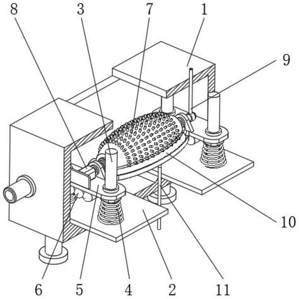
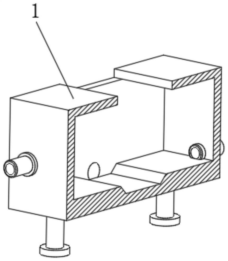
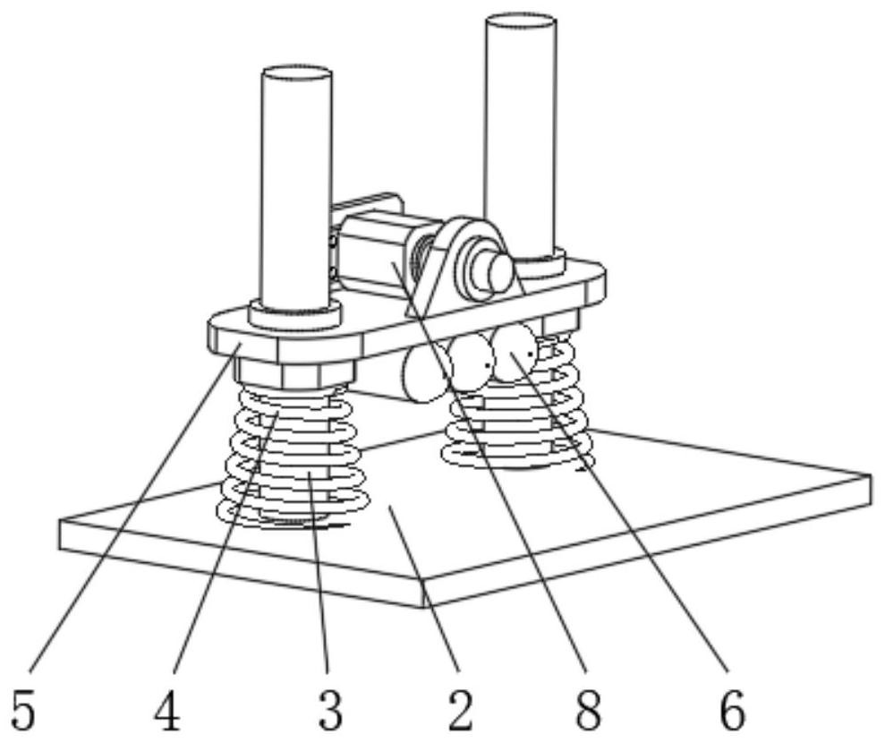
[0025] see Figure 1-6 , an oily sewage separation device, comprising a separation box 1, the bottom of the left and right sides of the inner cavity of the separation box 1 is fixedly equipped with support plates 2, and the front and rear sides of the top of the support plate 2 are fixedly installed with fixed pillars 3 , and the top of the fixed pillar 3 is fixedly connected to the top of the inner cavity of the separation box 1, the bottom of the outer surfa...


PUM

PropertyMeasurementUnit
depthaaaaaaaaaa

Abstract

The invention relates to the technical field of sewage treatment equipment, and discloses an oil-containing sewage separation device, which comprises a separation box body, supporting base plates arefixedly mounted at the bottoms of the left side and the right side of an inner cavity of the separation box body, and fixed supporting columns are fixedly mounted on the front sides and the rear sidesof the tops of the supporting base plates. The top ends of the fixed supporting columns are fixedly connected with the top of the inner cavity of the separation box body. According to the oil-containing sewage separation device, through the arrangement of an oil absorption bag body and an oil stain scraping plate, a felt structure on the oil absorption bag body can be used for adsorbing oil stains in oil-containing sewage, and the oil stains on the oil absorption bag body are removed under the rotary extrusion of the oil stain scraping plate; compared with an existing oil-water separation device, oil-water separation operation can be carried out in the flowing state of oil-containing sewage, standing operation does not need to be carried out on the oil-containing sewage any more, then theinternal space structure of the separation device is effectively reduced, and meanwhile the working efficiency of oil-water separation in the oil-containing sewage is improved.

Description

technical field [0001] The invention relates to the technical field of sewage treatment equipment, in particular to an oily sewage separation device. Background technique [0002] In the context of an increasingly prosperous society, with the improvement of people's living standards, the rapid development of the catering industry is constantly being driven, and the discharge of oily sewage caused by this is also increasing. Because there is a layer of grease floating on the surface of oily sewage , it is difficult to be degraded when it is discharged into the natural environment, and it can cut off the contact between the water source and the air, resulting in a decrease in the oxygen content in the water source, and it is easy to breed a large number of bacteria and viruses, thereby causing damage to the natural environment and water resources. Therefore, in order to meet the environmental protection discharge standards, it is necessary to perform oil-water separation befor...

Claims


Application Information

Patent Timeline
Patent Type & Authority Applications(China)
IPC IPC(8): C02F1/40C02F1/28B01D17/022
CPCB01D17/0202C02F1/28C02F1/40
Inventor 陶松娣
Owner 陶松娣
Why Eureka
Try Eureka