Anti-overturning steel bar support used for cantilever coping concrete pouring and installation method of steel bar support

An anti-overturning and concrete technology, which is applied in buildings, bridges, bridge construction, etc., can solve the problems of pile driving and pile pulling equipment with many labor resources, poor control of structural safety factor, poor economic benefits, etc., and achieves convenient and quick installation and disassembly , Improve operating efficiency and reduce labor costs

Active Publication Date: 2017-09-15
CCCC SHEC FOURTH ENG +1
View PDF9 Cites 4 Cited by
  • Summary
  • Abstract
  • Description
  • Claims
  • Application Information

AI Technical Summary

Problems solved by technology

[0006] When the floor-type cover beam support is high in the pier body, the steel pipe piles need to be driven into the soil layer or fall on the cap. If the driven steel pipe piles are used as the load-bearing structure, corresponding piling and pile pulling equipment are required and the cost is relatively high. Many human resources, this type of structure has poor economic benefits
[0007] Although the steel rod type cover beam support has good economic benefits, its stability is poor, and the structural safety factor is not easy to control

Method used


Image

  • Anti-overturning steel bar support used for cantilever coping concrete pouring and installation method of steel bar support
  • Anti-overturning steel bar support used for cantilever coping concrete pouring and installation method of steel bar support
  • Anti-overturning steel bar support used for cantilever coping concrete pouring and installation method of steel bar support

Examples


Embodiment Construction

[0047] The following non-limiting examples serve to illustrate the invention.

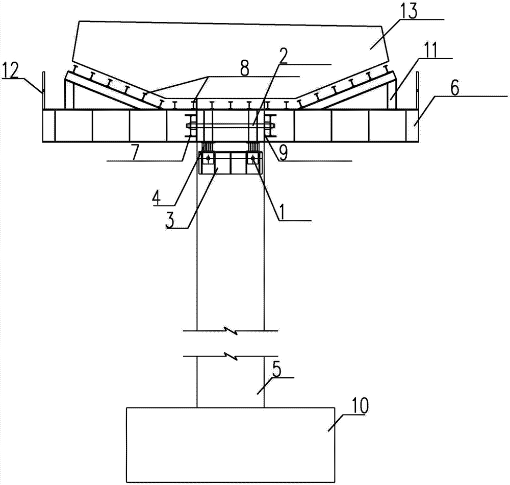
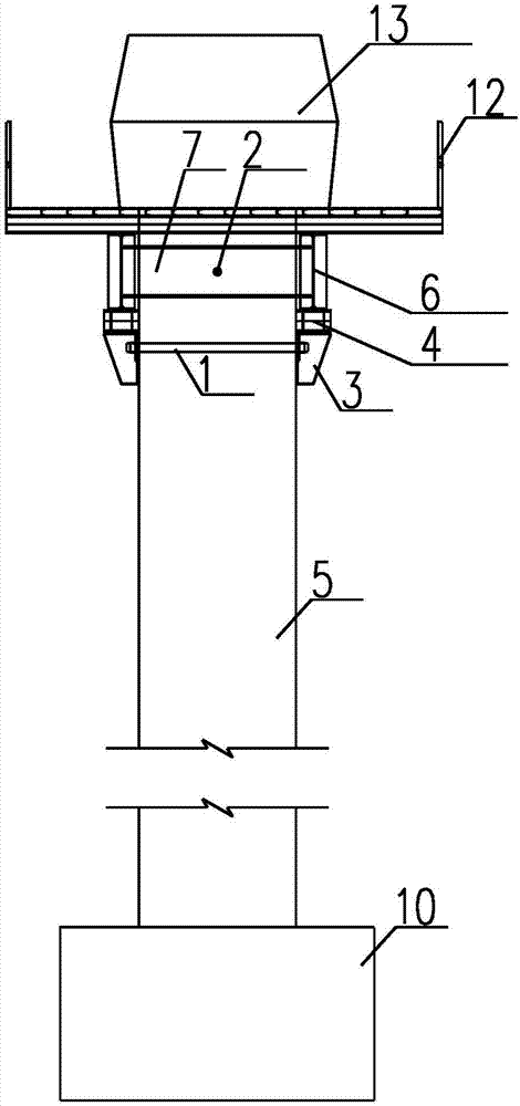
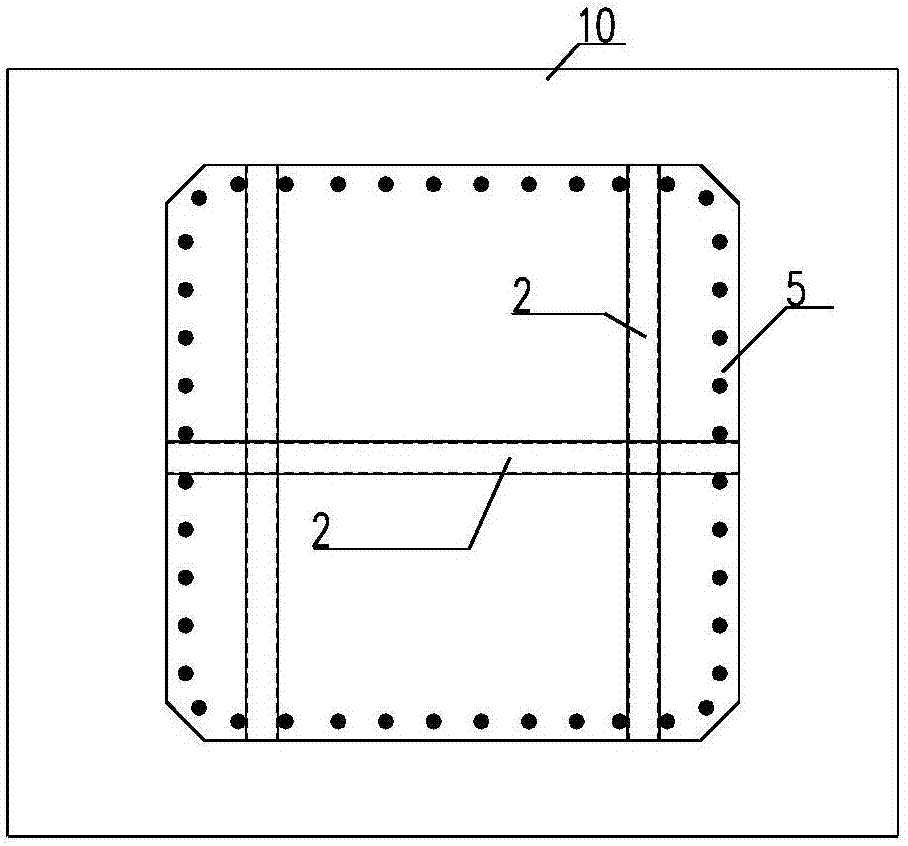
[0048] reference Figure 1 to 3 As shown, an anti-overturning steel bar support for cantilever cover beam concrete pouring is composed of six parts: load-bearing steel bar 1, anti-overturning steel bar 2, corbel 3, unloading block 4, support beam and formwork system. The pier body 5 is prefabricated with steel rod holes for the load-bearing steel rods 1 and the anti-overturning steel rods 2 to pass through. The load-bearing steel rods 1 are arranged horizontally along the longitudinal bridge direction at least 2 (as shown in the figure of this embodiment) , The anti-overturning steel rod 2 is horizontally arranged at least one along the transverse bridge direction, the load-bearing steel rod 1 also passes through the corbel 3 to fix the corbel 3 on the side of the pier 5, and the main beam 6 of the support beam is provided above the corbel 3, The main beam 6 is supported by the unloading block 4 arra...


PUM

PropertyMeasurementUnit
thicknessaaaaaaaaaa

Abstract

The invention discloses an anti-overturning steel bar support used for cantilever coping concrete pouring and an installation method of the steel bar support, and belongs to the field of building structure construction. The steel bar support is composed of load-bearing steel bars, anti-overturning steel bars, brackets, unloading blocks, a support beam and a formwork system. The load-bearing steel bars penetrate through the brackets and make the brackets fixed to the side face of a pier body, main cross beam bodies of the support beam are arranged above the brackets respectively and supported by the unloading blocks between the brackets and the main cross beam bodies, straining beam bodies of the support beam are arranged between the two main cross beam bodies on the outer side of the pier body in pairs, the straining beam bodies are attached to the two sides of the pier body and fixed to the main cross beam bodies in a bolted mode, and the anti-overturning steel bars penetrate through the two corresponding straining beam bodies and fixed between the two straining beam bodies. The installation method sequentially comprises the steps of prefabricating steel bar holes, installing the steel bars, installing the brackets, installing the main cross beam bodies, installing the straining beam bodies and the like. Anti-overturning measures are added, the steel consumption is greatly reduced, the operation efficiency is improved, and the labor cost is reduced.

Description

Technical field [0001] The invention belongs to the field of building structure construction, and is suitable for high piers, especially when the cover beam cantilever is large, the concrete is poured in place. Background technique [0002] At present, the following two types of support structures are generally used for cantilever cap beam concrete pouring: [0003] One is the use of floor-standing supports. The structures are all made of steel. It is necessary to set embedded parts on the bearing platform, or to drive the steel pipe piles of the supporting structure directly into the soil. Its characteristic is good stability. When the pier is high, it is necessary to install an attached wall on the pier, which will affect the appearance of the pier, and the economic benefits will not be good. [0004] The second type is the steel rod bracket. This type of structure does not use steel pipe piles as the load-bearing structure, which can save a lot of steel. The disadvantage is poor...

Claims


Application Information

Patent Timeline
Patent Type & Authority Applications(China)
IPC IPC(8): E01D21/00
CPCE01D21/00Y02A30/30
Inventor 李同杰张翼冯景发肖国祥刘金龙倪涛赵文喆郭玉强杨爽
Owner CCCC SHEC FOURTH ENG
Why Eureka
Try Eureka