
Cast-in-situ floor filled with special necking netted box-shaped cavity component

A box-shaped cavity, hollow floor technology, applied in building components, floor slabs, building structures, etc., can solve the problems of reducing construction production efficiency, slowing down the progress of the project, blocking troubles, etc. The effect of improving quality and construction efficiency

Inactive Publication Date: 2017-09-15
王清
View PDF9 Cites 1 Cited by
  • Summary
  • Abstract
  • Description
  • Claims
  • Application Information

AI Technical Summary

Problems solved by technology

Moreover, the built-in filling mandrel needs to be assembled and used at the construction site, which slows down the progress of the project and reduces the construction production efficiency
[0010] In view of the above-mentioned defects in various cast-in-place hollow floors in the prior art, a hollow floor with good overall performance with the comprehensive functional characteristics of the prior art is developed, so that the interior of the hollow floor can make full use of the concrete surface Tension, changing the shape of the steel grid to prevent the concrete mortar from penetrating into the steel grid, no buoyancy, good compatibility with concrete, and enhanced structural bearing capacity. The height of the inner space between the top and the bottom of the frame formed by supporting the steel mesh can bear the construction load of the top of the frame and the positive pressure of the concrete on the upper flange, realize the industrial production of the mesh box-shaped components, and overcome the existing technical problems. A large number of supports inside the frame and blockage of the frame are troublesome and costly, breaking through the existing technology of cast-in-place hollow floors has become a technical problem that needs to be solved urgently in the field of cast-in-place hollow floors

Method used


Image

  • Cast-in-situ floor filled with special necking netted box-shaped cavity component
  • Cast-in-situ floor filled with special necking netted box-shaped cavity component
  • Cast-in-situ floor filled with special necking netted box-shaped cavity component

Examples


Embodiment Construction

[0045] The technical solutions of the present invention will be clearly and completely described below in conjunction with the accompanying drawings in the present invention.

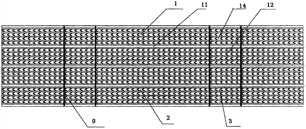
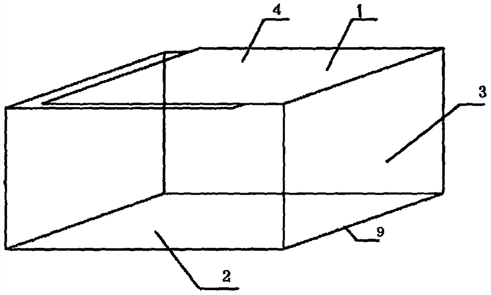
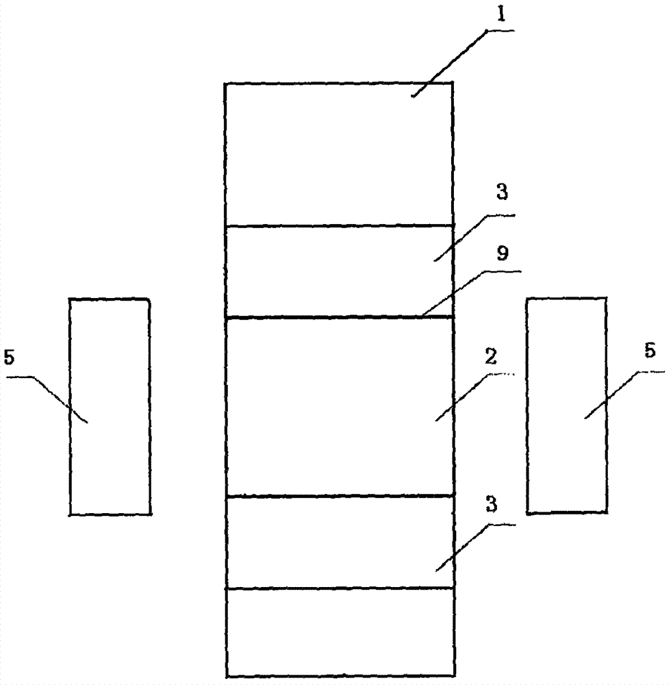
[0046] figure 1 and figure 2 Respectively, the plan view of the special closing net used in the special closing net box-shaped cavity member of the present invention and the schematic diagram of the main body of the special closing net box-shaped cavity member formed by folding the special closing net, as figure 1 As shown, the special closing mesh 1 used in the special closing mesh box-shaped cavity member includes two parts: a raised V-shaped reinforcing rib 11 and a steel mesh surface 14. The special closing mesh is cold-rolled steel strip used as a processing raw material for special It is made by machine stamping and stretching; when the special closing net is pressed in the vertical direction with a combined mesh box-shaped cavity member, the bending edge 9 at the bending place needs to be quant...


PUM


Abstract

The invention particularly relates to a cast-in-situ floor filled with a special necking netted box-shaped cavity component. The cast-in-situ floor is composed of a main beam, ribbed beams, an upper flange plate, a lower flange plate, steel bars and the special necking netted box-shaped cavity component. The special necking netted box-shaped cavity component is formed by assembling a special necking net, side sealing plates, supporting pieces and anti-floating pull pieces. The special necking net is coiled to form a main body of the special necking netted box-shaped cavity component provided with a box top face, two box body side faces and a box bottom face. The side sealing plates seal the two ends of the main body of the special necking netted box-shaped cavity component. The supporting pieces form a supporting skeleton in a closed space defined by the special necking net and the side sealing plates. The special necking net is adopted to manufacture the box-shaped cavity component for built-in filling of the cast-in-situ hollow floor, is good in composite compatibility with concrete, can completely prevent concrete mortar from permeating the box-shaped component and does not generate buoyancy, so that quality is improved, the construction auxiliary cost is reduced, and the construction convenient level and the engineering effect are greatly improved.

Description

technical field [0001] The invention relates to a hollow floor filled with cavity components, in particular to a cast-in-place hollow floor filled with special closed mesh box-shaped cavity components. Background technique [0002] With the development of technology in the field of construction engineering, the architectural needs of different spaces make the building structure gradually subdivided. Buildings such as underground garages, shopping malls, and office buildings are suitable for the application of large bays and beamless structures. The technology of cast-in-place concrete hollow floor was born based on such demand. In large-span and large-bay building structures, compared with traditional solid floors or prestressed floors, cast-in-place hollow floors have the advantages of lower floor height, large span, light weight, strong seismic performance, heat insulation, fire prevention and insulation. Good sound performance, good economy and many other advantages. At...

Claims


Application Information

Patent Timeline
Patent Type & Authority Applications(China)
IPC IPC(8): E04B5/36
CPCE04B5/36
Inventor 褚作勇王晓波朱海清闫景海
Owner 王清
Learn More