A protective structure for slip-form construction of exhaust chimney in painting workshop

A technology of exhaust chimney and protective structure, which is applied in the direction of housing structure support, housing structure support, and scaffolding supported by housing structure, etc., can solve the problems of increasing the probability of safety accidents, achieve green construction, improve safety factor, and maintain buffering effect of effect

Active Publication Date: 2019-06-18
CHINA MCC5 GROUP CORP
View PDF6 Cites 0 Cited by
  • Summary
  • Abstract
  • Description
  • Claims
  • Application Information

AI Technical Summary

Problems solved by technology

[0003] In the construction process of the automobile spraying workshop, it is necessary to use the sliding form technology to construct the chimney for exhausting the exhaust gas in the workshop. However, during the sliding form construction process, there will be more concrete blocks remaining on the support platform of the sliding form. The blocks will affect the construction operation of the construction workers, and they need to be cleaned regularly. As the height of the building increases, usually the construction workers will directly clean the concrete blocks on the support platform along the inner wall of the building, which is convenient and quick. However, it must be ensured that no one or equipment stays inside the building during cleaning, so as to avoid safety accidents caused by falling objects; However, there are still other people on the construction site who enter the lower area of ​​the building without knowing it, which greatly increases the probability of safety accidents

Method used


Image

  • A protective structure for slip-form construction of exhaust chimney in painting workshop

Examples


Embodiment 1

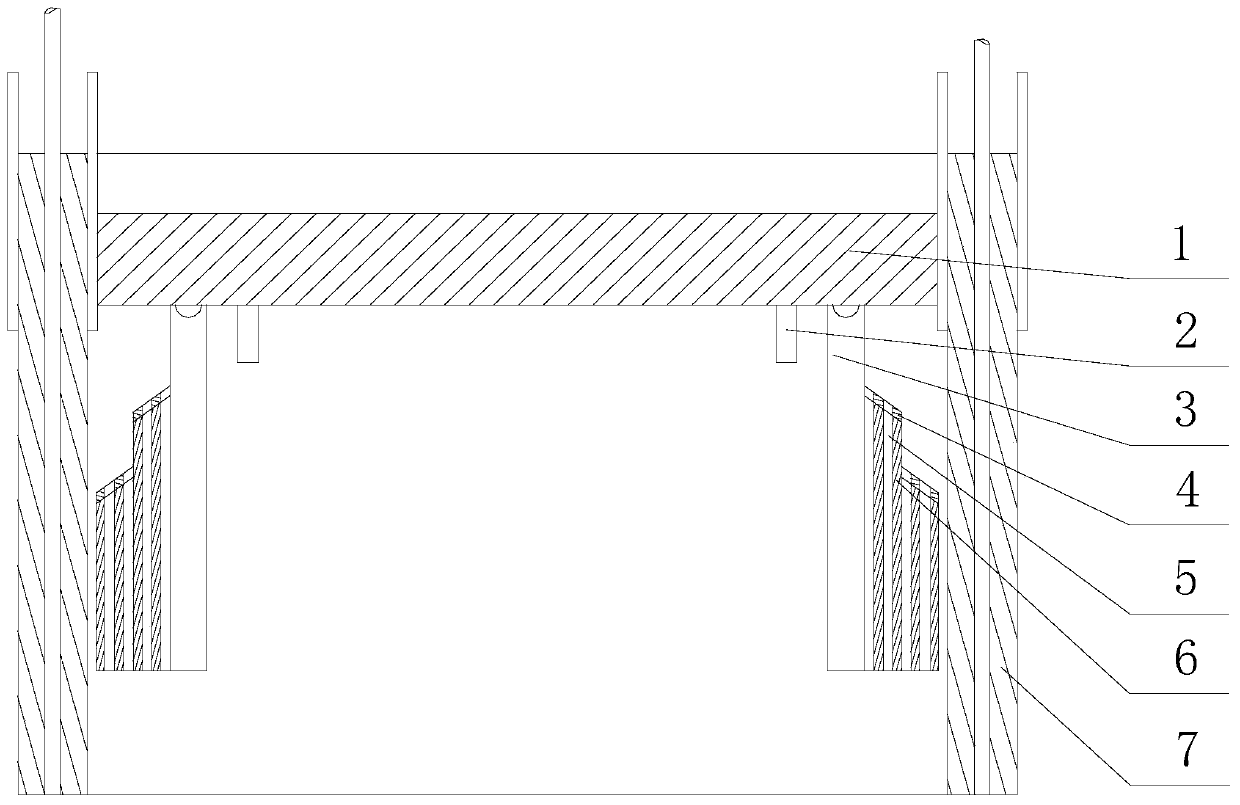
[0022] Such as figure 1As shown, this embodiment includes a rectangular support platform 1, four baffles 3 are hingedly arranged on the lower surface of the support platform 1 along the outline edge of the support platform 1, and on the outside of each of the baffles 3 At least two guide blocks 6 are arranged on the wall, and there is a rebound surface on the upper end surface of each guide block 6, and the rebound surface is inclined in a direction away from the support platform 1 along the horizontal direction, A flow passage 5 penetrating through the guide block 6 is opened on the guide block 6 along the vertical direction. In view of the prior art, when the support platform 1 cleans the concrete block, there is a gap between each end surface of the support platform 1 and the inner wall of the exhaust chimney 7, and the concrete block moves from top to bottom along the gap, and the falling process The concrete block will constantly collide with the inner wall of the exhaus...

Embodiment 2

[0027] Such as figure 1 As shown, in this embodiment, on the basis of Embodiment 1, a plurality of limiting plates 2 are provided on the lower surface of the support platform 1 , and the limiting plates 2 are facing the inner sidewall of the baffle plate 3 . When the large-diameter concrete block falls from the gap to contact with the guide block 6, the instantaneous impact force received by the guide block 6 is relatively large, and the impact force will drive the baffle plate 3 and the guide block 6 around the baffle plate 3. The hinge point makes a relatively large swing. At this time, before the baffle plate 3 and the guide block 6 return to their original positions, there is no blocking unit in the area below the gap to buffer the falling trend of the remaining concrete blocks, which causes the support platform 1 The protective structure below fails, and the applicant has provided a limit plate 2 corresponding to the baffle 3 on the lower surface of the support platform 1...


PUM


Abstract

The invention discloses a protective structure for slip-form construction of a gas exhausting chimney of a paint spraying workshop. The protective structure comprises a rectangular supporting platform. At least four baffles are correspondingly hinged to the lower surface of the supporting platform along the contour edge of the supporting platform. The outer side wall of each baffle is provided with at least two guiding blocks. The upper end surface of each guiding block is provided with a rebound face. Each rebound face is oblique towards a direction, far away the supporting platform, along a horizontal direction. A flow channel penetrating through the guiding block is arranged on each guiding block along a longitudinal direction. Through rebound buffering of the guiding blocks for large-diameter concrete blocks, the concrete blocks always fall downward along the inner wall of the gas exhausting chimney, and subtle-shaped concrete blocks or dust move downward vertically through the flow channels, so that the occurrence of the phenomenon of splashing everywhere of the concrete blocks or dust in the gas exhausting chimney is avoided, and the risk that constructors are injured by the concrete blocks can be eliminated as long as the upward climbing constructors walk upward by not clinging to the inner wall of the gas exhausting chimney.

Description

technical field [0001] The invention relates to the field of sliding formwork construction, in particular to a protective structure for sliding formwork construction of an exhaust chimney in a painting workshop. Background technique [0002] Sliding form engineering technology is a kind of construction with high degree of mechanization, fast construction speed, less site occupation, strong structural integrity, good seismic performance, safe operation guarantee, and remarkable comprehensive environmental and economic benefits in the construction of cast-in-place concrete structures in my country. technique, often referred to simply as "slip mode". Sliding formwork not only includes common templates or special templates and other tool-type templates, but also includes comprehensive technologies such as power sliding equipment and supporting construction technology. At present, hydraulic jacks are mainly used as sliding power. Under the synchronous action of a group of jacks, i...

Claims


Application Information

Patent Timeline
Patent Type & Authority Patents(China)
IPC IPC(8): E04G3/24E04G21/32
CPCE04G3/24E04G21/32
Inventor 贺光远李坤彭德坤
Owner CHINA MCC5 GROUP CORP
Why Eureka
Try Eureka