
Forklift equipment special for flammable ice on surface of sea floor

A forklift and equipment technology, applied in the field of seabed combustible ice mining equipment, can solve the problems of difficulty in fixing submersible pumps and difficulty in achieving sealing performance, and achieve the effects of small movement range, long maintenance-free time, and reduced mining costs

Active Publication Date: 2017-09-15
HANGZHOU YUNFENG IND DESIGN CO LTD
View PDF12 Cites 0 Cited by
  • Summary
  • Abstract
  • Description
  • Claims
  • Application Information

AI Technical Summary

Problems solved by technology

——In this patent solution, since the metal seal isolation shield is not completely closed only at the lower end and the shaft seal of the motor, the submersible pump must keep the motor at the upper liquid pump to ensure its sealing effect, so in use Generally, it is necessary to use fixing parts to fix the submersible pump in a stable position before it can be used. When this type of submersible pump is used on a deep seabed (for example, when the depth of combustible ice is mined on the seabed, the depth exceeds 300 meters), the fixing of this type of submersible pump It is very difficult, and it is difficult to achieve the effect of maintaining the sealing performance for a long time with ordinary submersible pumps.

Method used


Image

  • Forklift equipment special for flammable ice on surface of sea floor
  • Forklift equipment special for flammable ice on surface of sea floor
  • Forklift equipment special for flammable ice on surface of sea floor

Examples


Embodiment 1

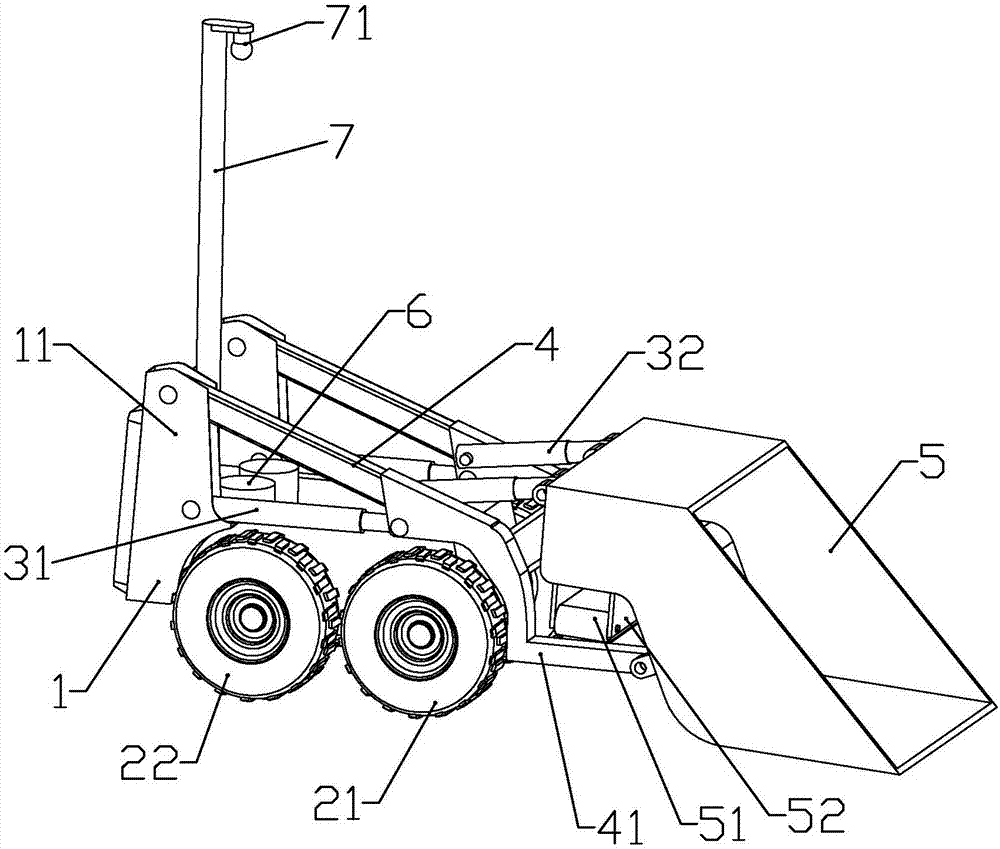
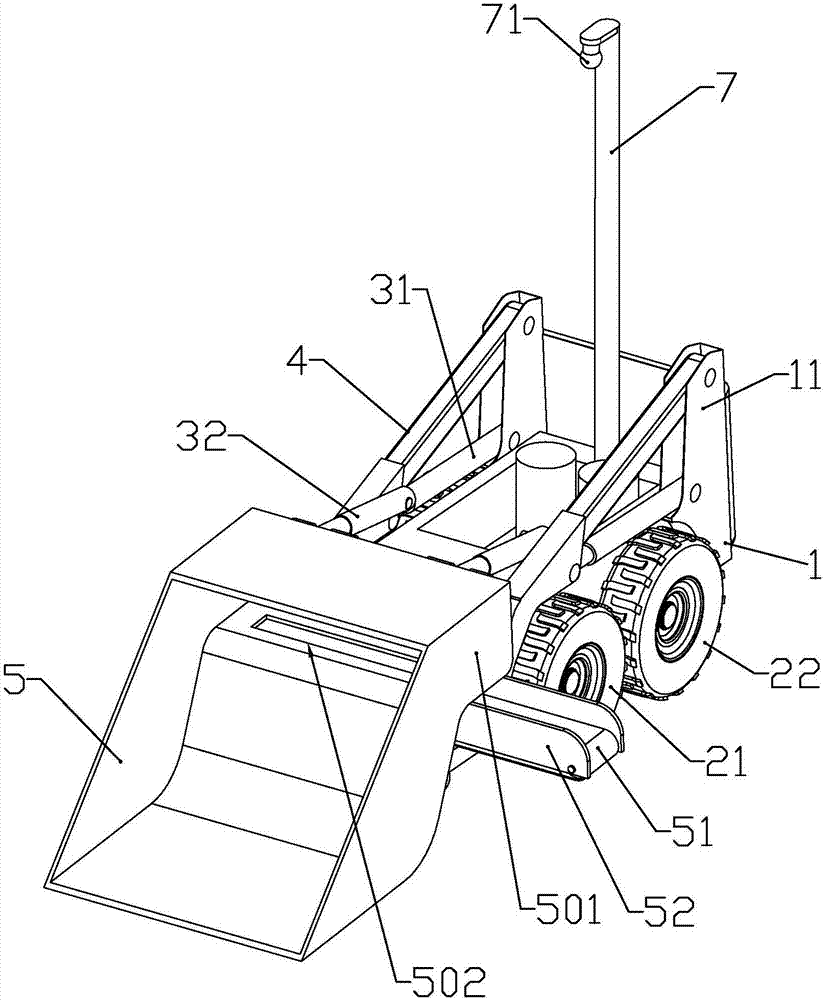
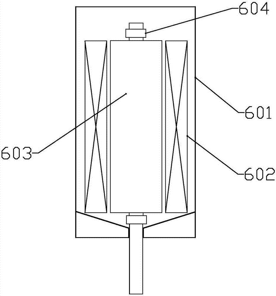
[0048] according to Figure 1 to Figure 3 As shown, this embodiment is a special forklift equipment for combustible ice on the surface of the seabed. It includes a vehicle body 1, two driving wheels 21 rotatably installed on both sides of the front of the vehicle body, and rotatably installed on both sides of the rear of the vehicle body. The two driven wheels 22; the vehicle body is equipped with two drive motors 6 respectively used to drive the two rotating wheels, the drive motor includes a hard non-magnetic metal material housing 601, fixed installation The winding 602 in the housing, and the rotor 603 installed in the housing through the rotor bearing 604 and located on the inner circumference of the winding rotor; the middle of the rotor is the output shaft, the lower end of the output shaft passes through the housing and the output shaft It is connected with the lower end of the shell through a sealed bearing; the lower end of the shell is in the shape of a funnel with a...

Embodiment 2

[0060] Combine Figure 4 As shown, this embodiment makes the following improvements on the basis of Embodiment 1: The drive motor is powered by a power generation device installed on the seabed; the power generation device includes an internal combustion engine 91, and a generator 92 connected to the output shaft of the internal combustion engine The intake end of the internal combustion engine is connected with a mixer 93, which is connected with an oxygen intake pipe and a natural gas intake pipe; the exhaust end of the internal combustion engine is connected with an exhaust pipe, and the other end of the exhaust pipe is connected with a cooling degassing tank 96; The other end of the oxygen gas inlet pipe is connected to an oxygen cylinder, and an air pump a95 is installed at the position of the oxygen gas inlet pipe near the mixer; the natural gas inlet pipe is connected with the gas outlet pipe of the combustible ice extraction well, and the natural gas inlet pipe is close t...

Embodiment 3

[0064] Combine Figure 5 with Image 6 As shown, this embodiment makes the following improvements on the basis of Embodiment 1 or 2: The power generation device and the controller are electrically connected through a suspended power transmission line 8, which includes a cable sheath 81 made of insulating material, An isolation layer is formed in the cable sheath along the length direction. Inside the cable sheath are located on both sides of the isolation layer, respectively, a transmission line cavity 811 and an inflatable cavity 812. The transmission line cavity is pierced with more than two transmission lines 82, so Two electrolytic conductors 84 are pierced in the gas-filled cavity, and the two electrolytic conductors are pierced in the water-absorbing sponge strip 83 used to isolate the two electrolytic conductors. The gas-filled cavity is filled with a weak alkaline solution, such as PH Sodium hydroxide solution with value 8.

[0065] The cable sheath is located in the air-...


PUM


Abstract

The invention belongs to the field of mining equipment for flammable ice on the surfaces of sea floors, and particularly relates to forklift equipment special for flammable ice on the surface of a sea floor. The forklift equipment comprises a forklift body, two driving wheels and two driven wheels, wherein the two driving wheels are rotationally installed on the two sides of the front portion of the forklift body, and the two driven wheels are rotationally installed on the two sides of the rear portion of the forklift body. Two driving motors used for driving the two rotary wheels are installed on the forklift body. The front end of the forklift body is connected with a bucket. A rear extending part is arranged on the upper portion of the rear end of the bucket. A strip-shaped opening in the left-right direction of the bucket is formed in the lower end of the rear extending part. A conveying belt which is arranged in the left-right direction of the bucket is installed on the lower portion, corresponding to the lower portion of the strip-shaped opening, of the rear extending part. The bucket is used for lifting the crushed solid flammable ice, so that the solid flammable ice is transferred onto the conveying belt. Compared with the other modes, the action ranges of all executive components are small, so that the situation that the solid flammable ice is decomposed in the process of being conveyed to a flammable ice mining well is avoided.

Description

Technical field [0001] The invention belongs to the field of seabed combustible ice mining equipment, and specifically relates to a special forklift equipment for seabed surface combustible ice. Background technique [0002] In the process of mining combustible ice on the seafloor surface, it is necessary to break the combustible ice into small pieces and then load it into a sealed tank and then transport it to the sea. So far, no public literature has found that it is suitable for long-term combustible ice mining on the seafloor surface. device of. As a mechanical device working in deep water, its executive components generally use motors as driving forces. [0003] On the other hand, the document number CN102195387B discloses a sealing structure of a submersible pump, which includes a conventional structure of a hydraulic pump driven by a motor driven by a rotor and a stator with embedded windings through its rotating shaft, and located at the outermost Layer of protective jack...

Claims


Application Information

Patent Timeline
IPC IPC(8): E21C50/00E02F3/38E02F9/22
CPCE02F3/382E02F9/22E21B41/0099E21B43/01E21C50/00F02B63/04H02K5/10
Inventor 李峰喻文武梁嘉麟
Owner HANGZHOU YUNFENG IND DESIGN CO LTD
Learn More