Coaxial gas injection valve with floating valve seat and with adjustable circulation section area

A technology of gas injection valve and floating valve seat, which is applied in the direction of engine components, engine control, combustion engine, etc., can solve the problems of error accumulation, injection valve leakage, injection valve difficult to debug, etc., to reduce flow loss and increase flow coefficient , the effect of improving reliability

Active Publication Date: 2017-09-15
HARBIN ENG UNIV
View PDF7 Cites 4 Cited by
  • Summary
  • Abstract
  • Description
  • Claims
  • Application Information

AI Technical Summary

Problems solved by technology

Injection valves need to work for thousands of hours under harsh working conditions such as high temperature and high pressure, and maintenance work such as disassembly will lead to gradual accu

Method used


Image

  • Coaxial gas injection valve with floating valve seat and with adjustable circulation section area
  • Coaxial gas injection valve with floating valve seat and with adjustable circulation section area
  • Coaxial gas injection valve with floating valve seat and with adjustable circulation section area

Examples


Embodiment Construction

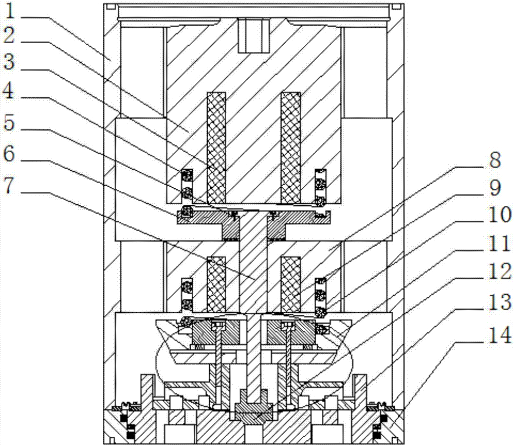
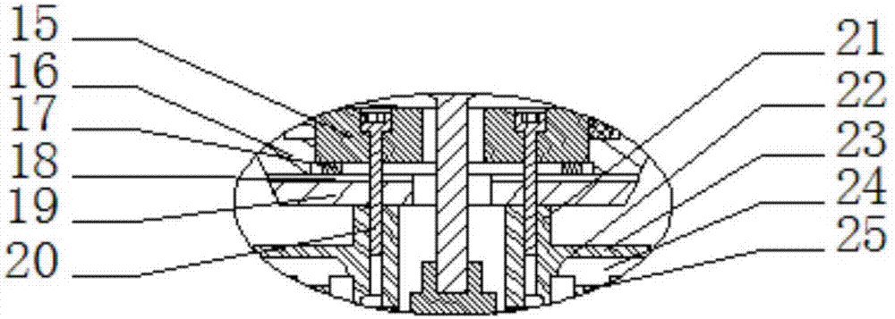
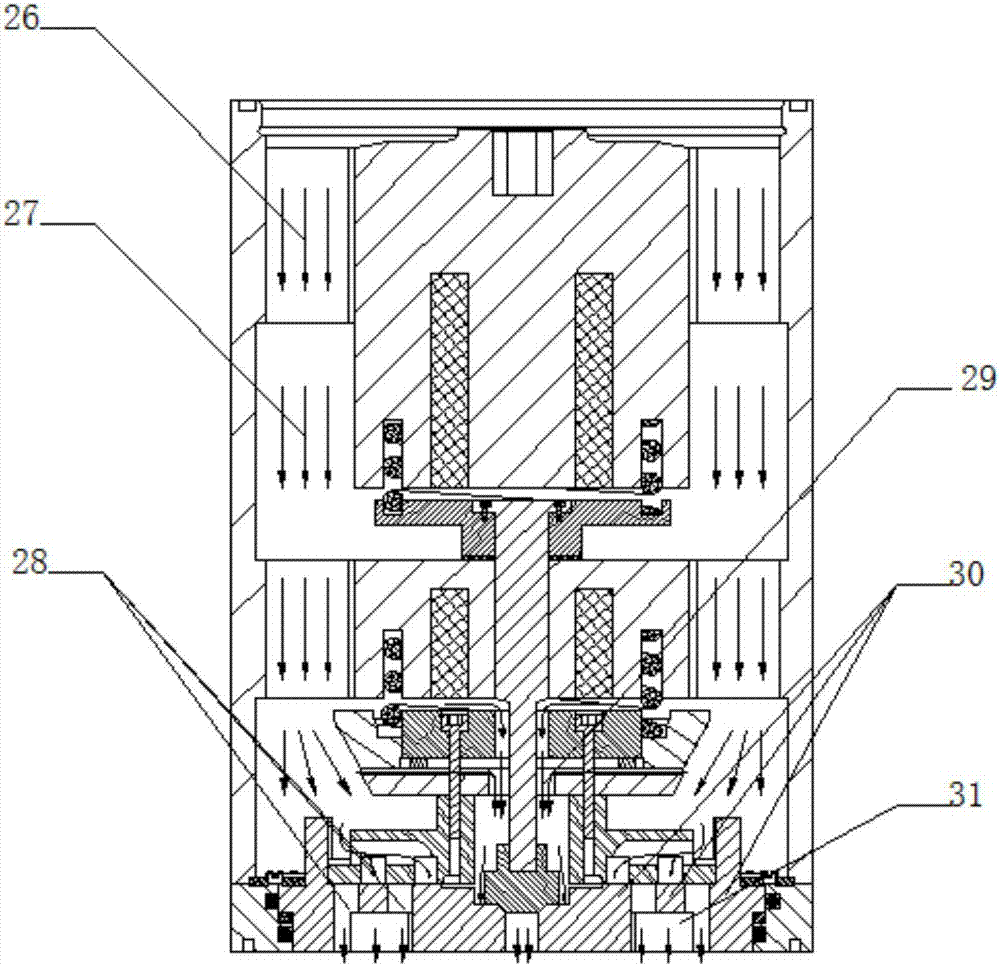
[0018] The present invention is described in more detail below in conjunction with accompanying drawing example:

[0019] to combine Figure 1-6 , figure 1 It is a schematic diagram of the overall structure of the coaxial gas injection valve with adjustable flow cross-sectional area with a floating valve seat of the present invention, including a valve body 1, a main electromagnet, a secondary electromagnet, a valve stem 7, a small valve core 12, and a T-shaped armature 6 , spool assembly 11, floating valve seat 14 four parts. The main electromagnet 2 is connected together with the valve body 1 through the upper thread. The main electromagnet mainly consists of an iron core 8 and a coil 9. Both sides of the iron core 8 are provided with annular grooves for arranging the main return spring 10 , and the valve core assembly 11 is arranged under the iron core 8 . The secondary electromagnet is mainly composed of a secondary iron core 2 and a secondary coil 3 . It is character...


PUM


Abstract

The invention aims at providing a coaxial gas injection valve with a floating valve seat and with the adjustable circulation section area. Through a double-valve-element and double-electromagnet controlled structure, the adjustable gas injection flow is achieved. Through a floating valve seat structure, the function that reverse leakage caused by unbalanced inner pressure and outer pressure of the gas injection valve is avoided is achieved, and work reliability of the gas injection valve is guaranteed. Through cooperation of an outer guiding structure, an inner flow guiding cavity and a pressure balance groove, perpendicularity of valve elements is guaranteed, stable work of gas flow is achieved, work is reliable, and the high response speed is achieved. The mixed gas inflow manner of direct gas inflow through an axial main gas groove and gas inflow through a circumferential gas supplementing hole, large flow is achieved, the gas supply efficiency of an engine is effectively improved, meanwhile gas flow interference can be avoided, and stability of a gas path is achieved. Through a multi-girdle structure between the valve elements and the valve seat, face sealing of the gas injection valve is achieved, and reliability is high.

Description

technical field [0001] The invention relates to a gas injection valve, in particular to a gas injection valve of a natural gas engine gas system. Background technique [0002] The problem of environmental pollution is becoming more and more serious, the requirements for emission indicators are becoming more and more stringent, and the demand for high-power gas generators in the market continues to grow. With the use of large-scale gas engines, the manufacture, maintenance and repair of key components have become important factors restricting the development of gas engines, and gas injection valves are such key components. The gas injection valve is one of the core components of gas fuel electronically controlled multi-point injection gas engine including dual fuel engine. Power and emissions have a very important impact. Injection valves need to work for thousands of hours under harsh working conditions such as high temperature and high pressure, and maintenance work such ...

Claims


Application Information

Patent Timeline
IPC IPC(8): F02M21/02F02D19/06
CPCF02D19/0686F02M21/0248F02M21/0254F02M21/0257F02M21/0269Y02T10/30
Inventor 宋恩哲王毓源范立云姚崇费红姿
Owner HARBIN ENG UNIV
Why Eureka
Try Eureka