Small-power ventilator directly driven by permanent-magnet synchronous electromotor

A permanent magnet synchronous and electric motor technology, applied to electrical components, electric components, machines/engines, etc., can solve problems such as small size, complex detection circuits and programs

Pending Publication Date: 2017-09-15
广州市先河技术工程有限公司
View PDF7 Cites 2 Cited by
  • Summary
  • Abstract
  • Description
  • Claims
  • Application Information

AI Technical Summary

Problems solved by technology

In view of the fact that the ventilation fan is driven by an asynchronous motor and the efficiency is relatively low, the low-power ventilation fan proposed by the applicant in the prior application CN201510395121.5 is directly driven by a permanent magnet synchronous motor, which is energy-saving and has a small volume, and has a relatively high speed in the predetermined direction of rotation. It has good starting and running performance, and there is no need to set a separate rotor position detection element, but in order to make it start and run according to the predetermined direction, it needs to control its power supply. The first step is pre-positioning-determining the magnetic pole of the permanent magnet rotor relative to the magnetic pole of the stator. position, and then according to the detection result and the predetermined direction, the voltage of the corresponding polarity waveform is applied to the stator, and the detection circuit and program are more complicated

Method used


Image

  • Small-power ventilator directly driven by permanent-magnet synchronous electromotor
  • Small-power ventilator directly driven by permanent-magnet synchronous electromotor
  • Small-power ventilator directly driven by permanent-magnet synchronous electromotor

Examples


Embodiment Construction

[0043] The ventilating fan in the embodiment of the present invention is improved on the basis of the embodiment described in the patent application CN201510395121.5 published by the applicant earlier.

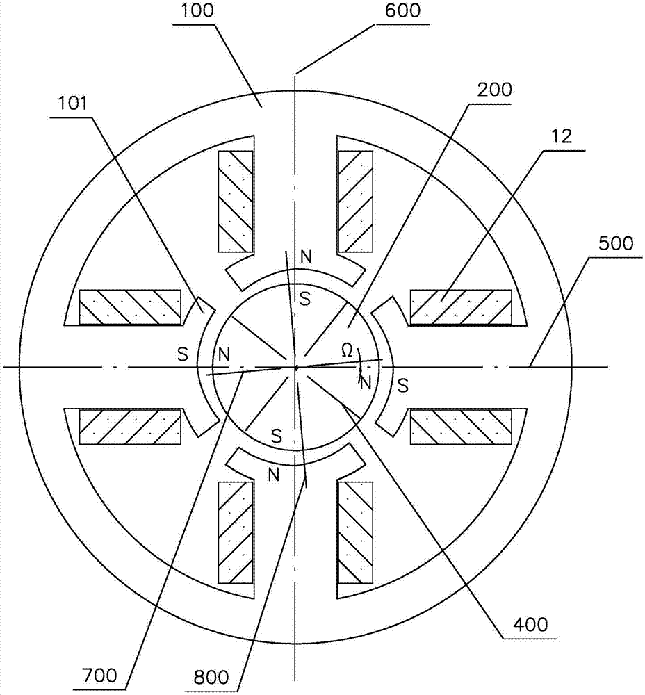
[0044] The basic mechanical structure of the ventilating fan in the embodiment of the present invention is as follows Figure 7 As shown, it inherits the CN201510395121.5 publication specification figure 1 The structure shown includes:

[0045] ——Motor 2 fixed to the casing;

[0046] ——The axial flow impeller 1 which is directly connected to the output shaft of the motor and rotates counterclockwise. It has 4 blades; according to wind pressure requirements, the number of blades can also be 3, 5 or 6, but it is better not to exceed 8. And as many as possible odd number of slices to reduce vibration and noise. The impeller is injection molded with a diameter of 100mm. The impeller should not be larger, and the moment of inertia should be as small as possible to match the starting to...


PUM


Abstract

The invention provides a small-power ventilator directly driven by a permanent-magnet synchronous electromotor. The small-power ventilator comprises an impeller and the electromotor directly driving the impeller, wherein the impeller performs directional rotation and is formed through injection moulding, a stator winding of the electromotor is connected with an alternating-current power source according to the stipulated winding direction, a rotor is a permanent magnet rotor and is of the same number of poles as that of a stator, and in a free state, the axes of all poles of the rotor are deviated by an acute angle in the predetermined rotation direction with the axis of the closest pole of the stator being the reference. The alternating-current power source supplies power to the stator winding through a switch controlled by a control circuit. When the number of poles of the stator is four, the diameter of the impeller is smaller than or equal to 100 mm, or when the number of poles of the stator is six, the diameter of the impeller is smaller than or equal to 130 mm, or when the number of poles of the stator is eight, the diameter of the impeller is smaller than or equal to 150 mm; a built-in program of the control circuit comprises the step that the switch is driven according to the detected signal so as to control the alternating-current power source to supply power to the stator winding; and before the ventilator is started, one pole face of a stator iron core represents magnetism of the stipulated polarity. By means of the design, the prepositioning detection process performed when a ventilator of the traditional technology is started is omitted, performance is improved, and the cost is lowered.

Description

Technical field [0001] The invention relates to a low-power ventilating fan directly driven by a permanent magnet synchronous motor, in particular to the coordination of its mechanical structure, electromagnetic structure and control method; IPC classification belongs to F04D25 / 08. Background technique [0002] Ventilation fans are widely used and have a long operating time, and there is an urgent need for low-cost manufacturing and energy-saving operation. In view of the fact that the ventilation fan is driven by an asynchronous motor and the efficiency is low, the applicant's previous application CN201510395121.5 proposed a low-power ventilation fan directly driven by a permanent magnet synchronous motor, which saves energy and is small in size, and has a relatively high degree of rotation in a predetermined direction of rotation. Good starting and running performance, and no separate rotor position detection element is required, but in order to start and run according to the p...

Claims


Application Information

Patent Timeline
Patent Type & Authority Applications(China)
IPC IPC(8): F04D25/08F04D29/26F04D27/00H02K7/14
CPCH02K7/14F04D25/0646F04D25/08F04D27/00F04D29/26
Inventor 叶露微
Owner 广州市先河技术工程有限公司
Why Eureka
Try Eureka