Visual detection system and detection method for LED lamp filament spot-welding correction

A technology for LED filament and visual inspection, applied in the field of visual inspection system, can solve the problems of unstable quality, low efficiency of LED filament production method, low product accuracy, etc., and achieve the effect of improving welding accuracy and improving sorting speed and accuracy.

Inactive Publication Date: 2017-09-15
SOUTH CHINA UNIV OF TECH
View PDF8 Cites 7 Cited by
  • Summary
  • Abstract
  • Description
  • Claims
  • Application Information

AI Technical Summary

Problems solved by technology

[0004] The primary purpose of the present invention is to overcome the problems of low efficiency, low product precision and unstable quality of the existing manual-based LED filament production methods, and to provide a visual inspection system for spot welding correction of LED filaments. The system can not only automatically correct the position of the filament during the spot welding process of the LED filament to improve the welding accuracy, but also realize the high-speed visual inspection function during the sorting process of defective products to improve the sorting speed and accuracy of defective products

Method used


Image

  • Visual detection system and detection method for LED lamp filament spot-welding correction
  • Visual detection system and detection method for LED lamp filament spot-welding correction

Examples


Embodiment 1

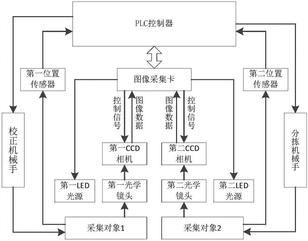
[0037] Such as figure 1 As shown, a visual detection system for LED filament spot welding, including: PLC controller, image acquisition card, first position sensor, second position sensor, calibration manipulator, sorting manipulator, first LED light source, second LED light source, first optical lens, second optical lens, first CCD camera, second CCD camera. The first CCD camera, the second CCD camera, the first optical lens, the second optical lens, the first LED light source, and the second LED light source jointly form a visual acquisition system, and the welding process Image acquisition with the products of the sorting process.

[0038] The image acquisition card is directly connected with the first LED light source and the second LED light source, the first CCD camera and the second CCD camera, and the image acquisition card controls the first LED light source and the second LED light source. The switch of the second LED light source is used to cooperate with the acqu...

Embodiment 2

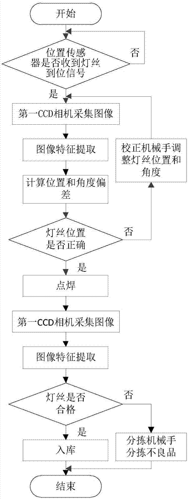
[0046] Such as figure 2 As shown, a visual detection method for LED filament spot welding correction, the specific workflow is as follows: When the acquisition object 1 reaches the designated welding position, the first position sensor will send the "detected object" message to the PLC controller Pulse signal, the PLC controller sends a trigger signal to the image acquisition card after calculation. After the image acquisition card detects this signal, it will immediately send an image acquisition command to the first CCD camera, and at the same time control the opening of the first LED light source. The first CCD camera transmits the collected image signal back to the image acquisition card, and the image acquisition card passes the image signal to the PLC controller to obtain the position deviation signal after processing, and the PLC controller processes the position deviation signal and sends correction to the calibration manipulator Signal, after the acquisition object i...


PUM


Abstract

The invention discloses a visual detection system and detection method for LED lamp filament spot-welding correction. The visual detection system comprises a PLC controller, an image acquisition card, two position sensors, a calibration manipulator, a sorting manipulator, two LED light sources, two optical lenses, and two CCD cameras. The CCD cameras, the LED light sources, and the optical lenses form a visual acquisition system to carry out image acquisition on products during a welding process and a sorting process; the collected image data are processed at the image acquisition card. The position sensors are installed in LED filament spot welding and sorting positions and are responsible for collecting position information of LED filaments and transmitting the information to the PLC controller. The PLC controller and the image acquisition card are connected by an RS232 bus; after obtaining of a processing result from the image acquisition card, the calibration manipulator and the sorting manipulator carry out corresponding operations, thereby completing precise welding and rapid sorting of the LED lamp filaments.

Description

technical field [0001] The invention relates to the technical field of intelligent control, in particular to a visual detection system and detection method for LED filament spot welding correction. Background technique [0002] In the 21st century, problems such as energy consumption, resource shortage and environmental degradation have swept the world, becoming the main contradiction affecting the world's economic and social development. It is an inevitable trend for energy saving and environmental protection to replace traditional lighting lamps with LED lamps, so the demand for LED lamps has been increasing in recent years. LED filament is the core component of LED lamps. At present, the production of LED filaments in China is mainly manual, with low efficiency and uneven quality, and the production capacity cannot be improved, resulting in high cost of LED lamps. [0003] The two most critical links in the production of LED filaments are spot welding and screening of de...

Claims


Application Information

Patent Timeline
Patent Type & Authority Applications(China)
IPC IPC(8): G01B11/00G01D21/00B07C5/10
Inventor 吴玉香王鹏
Owner SOUTH CHINA UNIV OF TECH
Why Eureka
Try Eureka