
Vision localization and navigation method and system for polling robot of transformer substation

An inspection robot and visual positioning technology, applied in the field of navigation, can solve the problems of limited area, high cost of navigation methods, and restricted travel range of inspection robots.

Inactive Publication Date: 2017-09-15
GUANGDONG UNIV OF TECH
View PDF5 Cites 32 Cited by
  • Summary
  • Abstract
  • Description
  • Claims
  • Application Information

AI Technical Summary

Problems solved by technology

The inspection robot platform uses magnetic sensors to realize navigation, but this navigation method is costly and not flexible enough; after the navigation route is determined, it needs to be manually constructed on site to bury the magnetic track. Once the magnetic track line is implemented, it is difficult to change; and in the substation environment The area where the magnetic track can be buried is limited, which is the main reason for restricting the driving range of the inspection robot, which makes the inspection robot have to collect images far away from the equipment, which introduces many problems for subsequent image processing and analysis
In addition, since the substation environment is a non-structural environment, people will enter from time to time for equipment maintenance, and there are vehicles entering, how to ensure that the inspection robot will not harm people, and avoid avoiding vehicles on the road, It is a must-have ability for a new generation of intelligent inspection robots

Method used


Image

  • Vision localization and navigation method and system for polling robot of transformer substation
  • Vision localization and navigation method and system for polling robot of transformer substation
  • Vision localization and navigation method and system for polling robot of transformer substation

Examples


Embodiment Construction

[0050] With the development of sensor technology and processor technology, robot technology is developing towards an increasingly intelligent direction. The formation and development of computer vision theory enables robots to have a visual system similar to human binoculars, allowing robots to obtain more environmental information based on the visual system. Visual navigation technology mainly includes monocular, binocular stereo vision, trinocular and multi-camera structures. Monocular vision mainly uses the image information collected by the camera to identify the signs in the structural scene, directly uses the image plane information to judge the scene, and also uses the method of motion-based three-dimensional information recovery to navigate based on the monocular camera structure. Stereo vision technology mainly uses the three-dimensional information reconstructed from two or more images, and on this basis, detects obstacles and detects road conditions, and finally rea...


PUM


Abstract

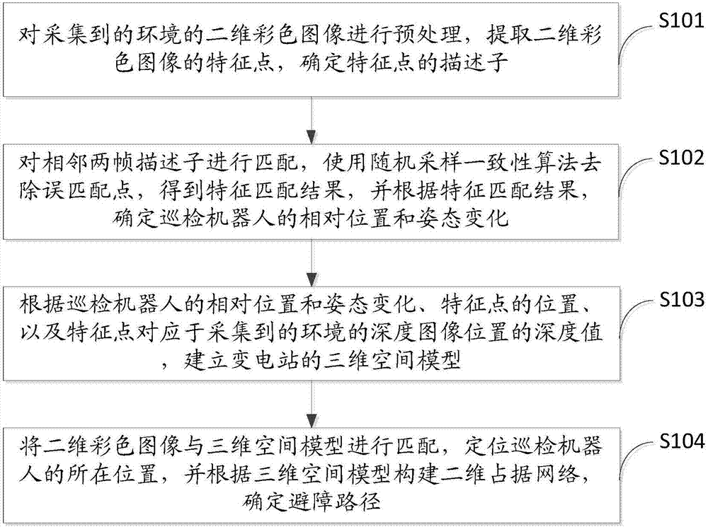
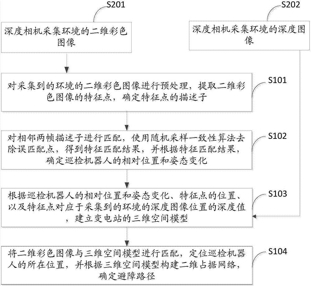
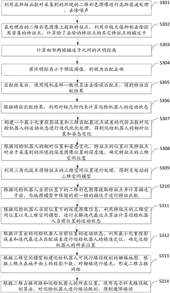
The invention discloses a vision localization and navigation method and system for a polling robot of a transformer substation. The vision localization and navigation method comprises the following steps: preprocessing a collected environmental two-dimensional colored image, extracting feature points, and determining descriptors of the feature points; matching the descriptors of two adjacent frames so as to obtain a feature matching result, and determining a relative position and posture change of the polling robot; establishing a three-dimensional space model of the transformer substation according to the relative position and posture change of the polling robot, the positions of the feature points and the depth values of the feature points corresponding to depth image positions; matching the two-dimensional colored image with the three-dimensional space model, locating the position of the polling robot, constructing a two-dimensional occupancy network, and determining an obstacle avoidance route. Based on image information analysis and relevant algorithms, the accurate position of the polling robot can be positioned, obstacles in a whole situation can be automatically detected, and the route can be planned according to the obstacles and the positions of the obstacles. The method is easy to implement, low in cost, good in stability and high in precision.

Description

technical field [0001] The invention relates to the field of navigation, in particular to a visual positioning and navigation method and system for a substation inspection robot. Background technique [0002] With the continuous development of social economy, the electricity consumption has increased sharply, so the length of transmission lines and the number of substations have increased sharply. Most of the safety monitoring of substations and transmission lines is done manually. Manual inspection of power equipment is labor-intensive and inefficient, and can no longer keep up with the pace of the times. In order to ensure safe and reliable power supply, the operation automation and modernization of power equipment have been increasingly manifest its urgency. With the rapid development of modern science and technology, various inspection robots have emerged as the times require, which can replace or assist traditional manual inspection operations, improve work efficiency,...

Claims


Application Information

Patent Timeline
Patent Type & Authority Applications(China)
IPC IPC(8): G01C21/20
CPCG01C21/20
Inventor 叶培楚李东王晓东曾宪贤张志超
Owner GUANGDONG UNIV OF TECH
Learn More