Supercharge Your Innovation With Domain-Expert AI Agents!

Pile side earth pressure detection and protection device and mounting method thereof

A protection device and earth pressure technology, applied in protection devices, field foundation soil survey, construction, etc., can solve problems such as inability to accurately reflect the horizontal resistance of undisturbed soil, vibration damage of pressure gauges, unfavorable steel pipe piles entering the soil, etc. , to achieve the effect of convenient and quick installation, avoid stress concentration, and protect from damage

Active Publication Date: 2017-09-19
中交二航局建筑科技有限公司 +1
View PDF10 Cites 1 Cited by
  • Summary
  • Abstract
  • Description
  • Claims
  • Application Information

AI Technical Summary

Problems solved by technology

This method cannot accurately reflect the horizontal resistance of the undisturbed soil because the force-bearing surface of the earth pressure box is not in direct contact with the soil around the pile, and the protective material epoxy resin is used to transmit the load under compression.
[0006] There is also a utility model patent with the patent number "CN205954721U" named "A device for embedding soil pressure gauges on the side of steel pipe piles for offshore wind power". , but in the process of pile sinking, under the action of large hammering energy and impact load, it is easy to cause vibration damage to the pressure gauge, and the addition of slots on the outer wall of the pile side increases the section of the pile body, and the resistance increases during the pile sinking process. Big, not conducive to steel pipe piles entering the soil

Method used


Image

  • Pile side earth pressure detection and protection device and mounting method thereof
  • Pile side earth pressure detection and protection device and mounting method thereof

Examples


Embodiment Construction

[0033] The present invention will be further described in detail below in conjunction with the accompanying drawings, so that those skilled in the art can implement it with reference to the description.

[0034] It should be noted that, in the description of the present invention, the terms "horizontal", "vertical", "upper", "lower", "front", "rear", "left", "right", "vertical", The orientation or positional relationship indicated by "horizontal", "top", "bottom", "inner", "outer", etc. is based on the orientation or positional relationship shown in the drawings, and is only for the convenience of describing the present invention and simplifying the description, and It is not to indicate or imply that the device or element referred to must have a particular orientation, be constructed in a particular orientation, or operate in a particular orientation, and thus should not be construed as limiting the invention.

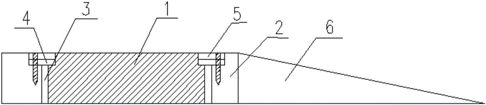
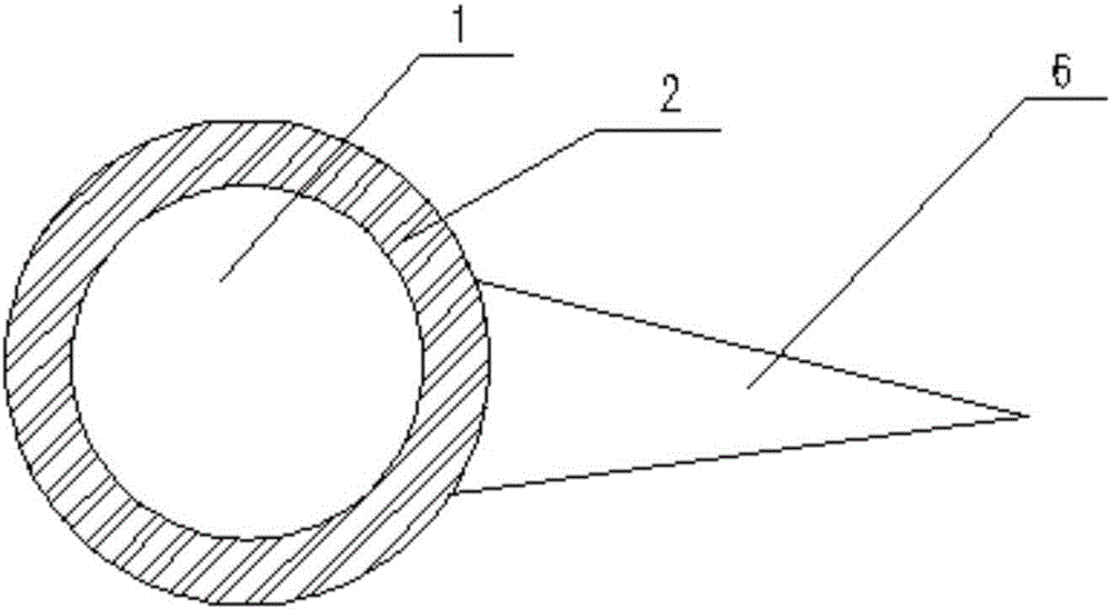
[0035] like figure 1 and figure 2As shown, the present invent...


PUM


Abstract

The invention discloses a pile side earth pressure detection and protection device which comprises an earth pressure sensor, a protection device body and a pressing plate. The shell of the earth pressure sensor is of a coaxial cylinder structure with the upper portion and the lower portion being formed integrally, and the diameter of the upper portion of the shell is smaller than that of the lower portion of the shell. The protection device body is of a hollow structure with both the upper portion and the lower portion being open. The upper portion and the lower portion of the hollow structure are coaxially arranged cylinder structures. The internal diameter of the upper portion of the hollow structure is larger than that of the lower portion of the hollow structure. The pressing plate is of a ring or ring-like structure. When the earth pressure sensor is placed in the hollow structure, the earth pressure sensor and the protection device body can be maintained in a relatively static state. The invention further provides a method for mounting the pile side earth pressure detection and protection device on a pile body. The earth pressure sensor is placed in the protection device body, the stress surface of the earth pressure sensor is in contact with earth mass smoothly and tightly, pressure is borne by the whole section, stress concentration is avoided, and the horizontal resistance of pile side earth is tested more accurately.

Description

technical field [0001] The invention relates to the field of pile foundation engineering, and the horizontal bearing capacity test of pile foundations. More specifically, the invention relates to a pile side soil pressure detection and protection device and installation method. Background technique [0002] Foundation piles are widely used in the foundations of bridges, docks, offshore wind power and other large buildings. Because they bear horizontal loads such as waves and currents and overturning moments, they have high requirements for horizontal bearing performance. The working performance of horizontal bearing piles is a problem of pile-soil interaction. Whether it is a fully buried pile or a partially buried pile, the resistance of the soil around the pile is used to bear the horizontal load. In the current calculation theory, the P-Y curve method guarantees The deformation coordination between piles and soils is achieved, and it is suitable for linear and nonlinear d...

Claims


Application Information

Patent Timeline
Patent Type & Authority Applications(China)
IPC IPC(8): E02D1/08E02D31/00E02D31/08E02D31/02
CPCE02D1/08E02D31/00E02D31/02E02D31/08E02D2200/1685E02D2600/10
Inventor 张阳陈海锋周焱斌关欣居炎飞明道贵郝艳广闵祥龙刘文锋刘长军
Owner 中交二航局建筑科技有限公司
Features
  • R&D
  • Intellectual Property
  • Life Sciences
  • Materials
  • Tech Scout
  • Unparalleled Data Quality
  • Higher Quality Content
  • 60% Fewer Hallucinations
Learn More