Bolt bonding surface real contact area measurement method and device

A bolt joint surface and contact area technology, which is applied in the direction of measuring devices, optical devices, instruments, etc., can solve the problems of destroying the surface shape of the joint surface, the inability to obtain the real joint area, and the accuracy of the joint surface area is not accurate enough to achieve area accuracy high effect

Active Publication Date: 2017-09-19
SHAANXI UNIV OF SCI & TECH
View PDF11 Cites 7 Cited by
  • Summary
  • Abstract
  • Description
  • Claims
  • Application Information

AI Technical Summary

Problems solved by technology

When the bolted connection bears the preload, the joint surface bears the normal load. In order to obtain the real joint surface area of ​​the bolted connection plane, in the current method of measuring the real area of ​​the joint surface by ultrasonic, the minimum diameter of the ultrasonic probe of the current displacement sensor is 0.9mm , resulting in inaccurate accuracy of the joint surface area obtained by measurement; using the method of eddy current displacement sensor, since the eddy current sensor cannot be directly located at the contact part of the joint surface, the measured displacement value often includes the deformation of the part, and the real joint area cannot be obtained; However, the method of using pressure-sensitive paper to measure the area of ​​the joint surface will destroy the real surface shape of the joint surface due to the intervention of the pressure-sensitive paper between the joint surfaces.

Method used


Image

  • Bolt bonding surface real contact area measurement method and device
  • Bolt bonding surface real contact area measurement method and device
  • Bolt bonding surface real contact area measurement method and device

Examples


Embodiment Construction

[0025] Below in conjunction with accompanying drawing, the present invention is described in further detail:

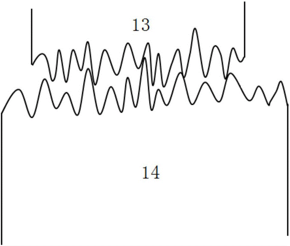
[0026] see figure 1 , the microscopic contact principle of the contact surface is: in the process of increasing the normal preload of the first part 13 and the second part 14, the asperity between the joint surfaces of the two parts deforms and starts to contact. increases, the deformation of the asperities in the contact area between the first part 13 and the second part 14 increases, and the gap in the contact area decreases until the measurable gap is zero.

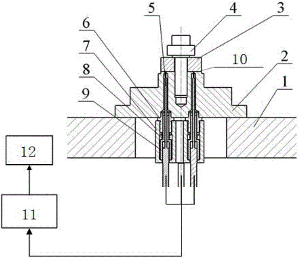
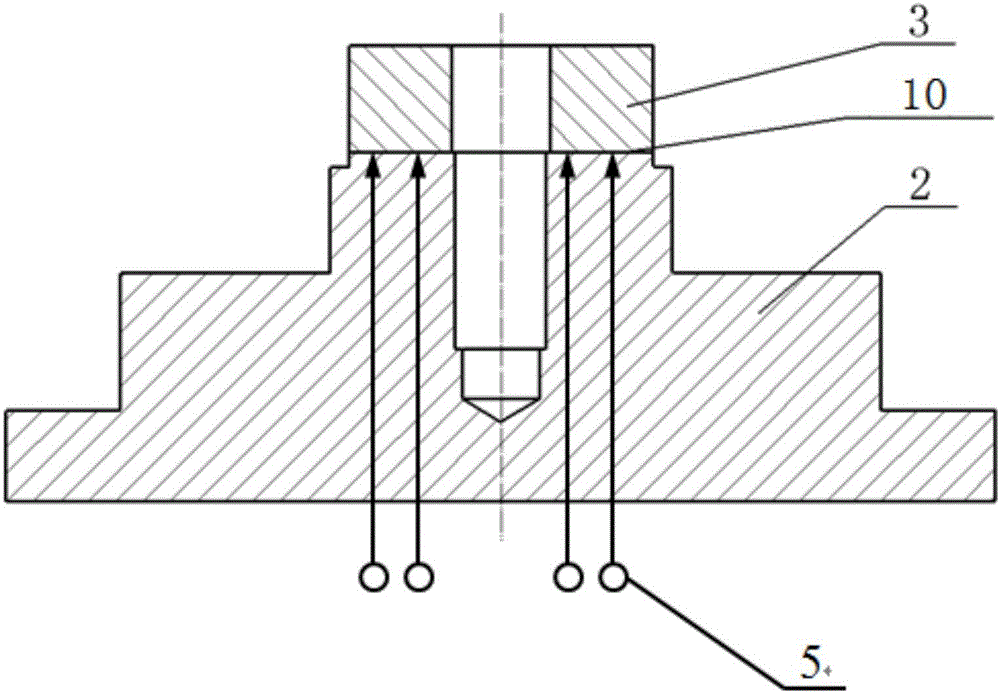
[0027] see figure 2 and image 3 , the present invention introduces high-precision nano-scale optical fiber sensors into the field of joint surface testing, and designs a set of test devices that use optical fiber sensors to measure the real joint area of ​​bolt joint surfaces, mainly including support box base 1, lower test piece 2, and upper test piece 3 , bolt 4, nano-scale optical fiber displacement se...


PUM


Abstract

The invention discloses a bolt bonding surface real contact area measurement method and device, the device comprises a support box base, a lower test piece is fixed to the support box base, an upper test piece is connected with the lower test piece through a bolt, a through hole is arranged in the support box base, a plurality of nano-scale optic fiber displacement sensors are arranged in the through hole, the nano-scale optic fiber displacement sensors are connected with the lower test piece through regulating components, the top parts of the nano-scale optic fiber displacement sensors passes through the lower test piece and are connected with a bonding surface of the upper test piece and the lower test piece, and the bottom parts of the nano-scale optic fiber displacement sensors are connected with a computer through a signal acquisition system. According to the invention, nano-scale optic fiber displacement sensors are adopted to perform a bolt bonding surface real contact area measurement test under pretension loading, and a test of bolt bonding surface predeformation varying with pretension loading can be performed at the same time.

Description

technical field [0001] The invention belongs to the technical field of joint surfaces of mechanical structures, and in particular relates to a device and method for measuring the real contact area of ​​a bolt joint surface based on an optical fiber sensor. Background technique [0002] The components in the mechanical system are generally not a continuous whole in order to facilitate processing and manufacturing, transportation and meet functional requirements, but a complete machine in which many parts are combined according to certain functional requirements. A large number of joints are inevitably formed between the joints. The joints include the joint surface and the structure of the two parts near the joint surface. The part of the surface layer where the two parts contact and undergo relative deformation is called the joint surface. Bolt connection is the most widely used connection method between machine tools and other complex machinery because it is easy to adjust t...

Claims


Application Information

Patent Timeline
IPC IPC(8): G01B11/28
CPCG01B11/28
Inventor 惠烨李鹏阳李艳
Owner SHAANXI UNIV OF SCI & TECH
Why Eureka
Try Eureka