Lower half part sand shell lower die of automobile rear suspension support

A technology of rear suspension bracket and sand shell, which is applied to casting molding equipment, casting molds, cores, etc., can solve the problems of uncertain shape and size of blanks, high requirements for skilled operation skills, and large labor workload of workers, reducing the The amount of machining, the reduction of casting defects, the effect of automatic production

Inactive Publication Date: 2017-09-22
YUZHOU KUNLUN MOLD CO LTD
View PDF1 Cites 0 Cited by
  • Summary
  • Abstract
  • Description
  • Claims
  • Application Information

AI Technical Summary

Problems solved by technology

[0002] The car rear suspension bracket is a part set on the rear axle of the car to carry the shock absorber and the suspension device. Due to the complicated structure and shape, most of its manufacturers use metal casting to produce blanks, and then perform machining to facilitate Obtain better stability and machining accuracy; Most of the existing automobile rear suspension brackets are cast with cast iron. The casting method is to first select the appropriate parting surface according to the design drawings of the automobile rear suspension A combined model with the same shape as the suspension bracket. Most of these combined models are bounded by the parting surface as the joint surface of the combined model. Most of these models are made of wood or aluminum for handling and processing; second, put the model into the sand box , fill in the casting sand and tamp it down, separate the sand box and take out the model, a cavity with the same shape as the model is formed in the middle of the sand in the sand box, and then make the casting channel and riser to complete the sand mold

Method used


Image

  • Lower half part sand shell lower die of automobile rear suspension support
  • Lower half part sand shell lower die of automobile rear suspension support
  • Lower half part sand shell lower die of automobile rear suspension support

Examples


Example Embodiment

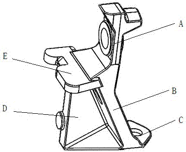
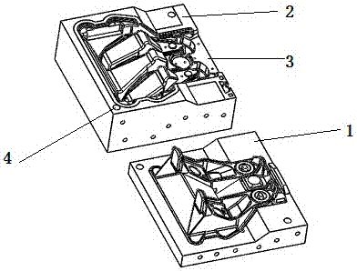
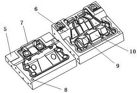
[0036] In order to further illustrate the technical solution of the present invention, the specific embodiments of the present invention will now be described with reference to the accompanying drawings, such as Figure 1 to Figure 9 According to the design drawings of the rear suspension bracket of the car, in this example, the rear suspension bracket of a medium-sized car is taken as an example. The rear suspension bracket of the car is divided into the upper part and the lower part with the transverse rib plate as the interface, and the shape of the rear suspension bracket of the car The size is enlarged by 8-12 mm, and the upper sand shell upper mold 1 and the upper sand shell lower mold 2, the lower sand shell upper mold 3, and the lower part of the upper sand shell mold and the lower half of the sand shell mold of the automobile rear suspension bracket are made respectively The lower sand shell mold 4 is made into the upper sand shell of the automobile rear suspension brac...


PUM


Abstract

The invention discloses a lower half part sand shell lower die of an automobile rear suspension support, and the lower half part sand shell lower die is suitable for an automobile rear suspension support lower half part sand shell die. The lower half part sand shell lower die comprises a die plate, a die cavity, a positioning hole and a half sand inlet. The die plate is located on the periphery of the die cavity and made of steel and iron materials. The die cavity is formed in the die plate, and the shape of the inner surface of the die cavity is the same as the appearance of a lower half part of the automobile rear suspension support. The positioning hole is formed in the die plate and corresponds to a positioning hole in a lower sand shell upper die. After the positioning holes are aligned, the thickness of a sand shell is formed through a lower half part upper die cavity and a lower half part lower die cavity. The half sand inlet is formed in the die plate edge position between the two die cavities, and a sand inlet is formed through combination of the half sand inlet and a half sand inlet in a lower half part upper die. The lower half part sand shell lower die has the function that the lower half part sand shell lower die can be combined with the lower half part sand shell upper die of the automobile rear suspension support for manufacturing of a lower half part sand shell of the automobile rear suspension support.

Description

technical field [0001] The invention belongs to the field of vehicle production, and in particular relates to a sand shell lower mold of a sand shell mold for the lower half of an automobile rear suspension support in a blank manufacturing method of an automobile rear suspension support. Background technique [0002] The car rear suspension bracket is a part set on the rear axle of the car to carry the shock absorber and the suspension device. Due to the complicated structure and shape, most of its manufacturers use metal casting to produce blanks, and then perform machining to facilitate Obtain better stability and machining accuracy; Most of the existing automobile rear suspension brackets are cast with cast iron. The casting method is to first select the appropriate parting surface according to the design drawings of the automobile rear suspension A combined model with the same shape as the suspension bracket. Most of these combined models are bounded by the parting surfa...

Claims


Application Information

Patent Timeline
IPC IPC(8): B22C7/00B22C9/22
CPCB22C7/005B22C9/22
Inventor 李向阳
Owner YUZHOU KUNLUN MOLD CO LTD
Why Eureka
Try Eureka