Lower die of bearing seat precoated sand die

A technology of coated sand and bearing seats, which is applied in the direction of manufacturing tools, casting molding equipment, casting molds, etc., can solve problems such as complex structures and shapes, achieve the effects of reducing casting defects, realizing automatic production, and improving yield

Inactive Publication Date: 2017-09-22
YUZHOU KUNLUN MOLD CO LTD
View PDF1 Cites 0 Cited by
  • Summary
  • Abstract
  • Description
  • Claims
  • Application Information

AI Technical Summary

Problems solved by technology

[0002] The bearing seat is the supporting part of the bearing, usually in the shape of a box; such as figure 1 As shown, the inner cavity of the bearing seat needs to adapt to the shape of the outer ring of the bearing, and the outer shell of the bearing seat needs to adapt to various installation environments, so its structure and shape are relatively complicated. Most of its manufacturers use metal casting to produce blanks, and then perform machining , in order to obtain better stability and processing accuracy; most of the existing bearing seat blanks are cast with cast iron, the casting method is firstly to select the appropriate parting surface according to the design drawings of the bearing seat, and to make the same shape as the bearing seat Combined model, most of this combined model is bounded by the parting surface as the joint surface of the combined model. Most of these models are made of wood or aluminum for handling and processing; second, put the model into the sand box and fill it with casting sand And tamping, the sand box is separated and taken out the model, a cavity with the same shape as the model

Method used


Image

  • Lower die of bearing seat precoated sand die
  • Lower die of bearing seat precoated sand die
  • Lower die of bearing seat precoated sand die

Examples


Example Embodiment

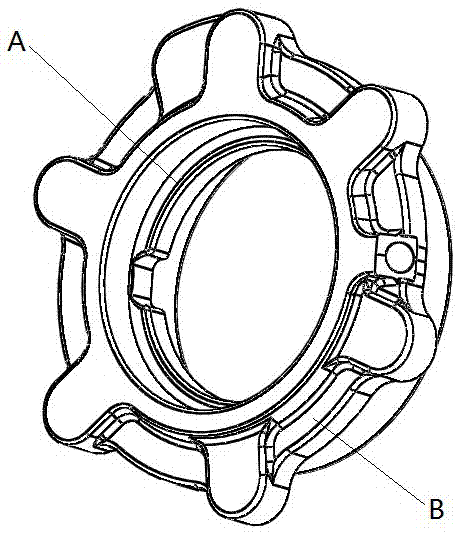
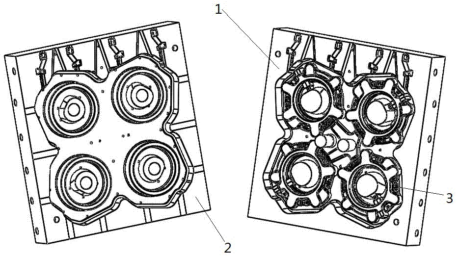
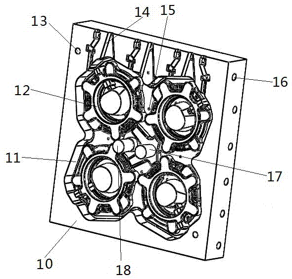
[0024] In order to further illustrate the technical solution of the present invention, the specific embodiments of the present invention will now be described with reference to the accompanying drawings, such as Figure 1 to Figure 4 According to the design drawings of the bearing seat, in this example, a small bearing seat is taken as an example, the number of bearing seats is selected as four, and the bearing seats are arranged uniformly, and the outer dimension of the bearing seat is enlarged by 8-12 mm to make the bearing seat coated sand mold In this example, the horizontal center plane of the bearing seat is selected as the casting parting surface, and the parting surface is used as the boundary, and the upper mold 1 and the lower mold 2 are respectively made from the bearing seat coated sand mold with the bearing seat parting surface as the center; On the upper mold 1 in this example, a steel plate with a thickness of 50 mm is used as the upper template 10, and the upper ...


PUM


Abstract

The invention discloses a lower die of a bearing seat precoated sand die and belongs to the field of mechanical equipment production. The lower die comprises a lower die plate, a lower outer cavity, lower inner cavities, positioning holes, sand inlets, ventilation holes and installation holes. The lower die plate is located on the periphery of the lower outer cavity, and the lower outer cavity is located in the outer side of the interior of the lower die plate. The lower inner cavities are located in the inner side of the interior of the lower die plate. The positioning holes are located in the lower die plate. The sand inlets are formed in the positions, at the upper portion of the lower outer cavity, on the lower die plate and communicate with the interior of the lower outer cavity and the interiors of the lower inner cavities. The ventilation holes are formed in the lower die plate and communicate with an overflow channel between the lower outer cavity and the lower inner cavities. The installation holes are formed in the lower die plate and are matched with an installation plate of an automatic sand shell forming machine. The lower die of the bearing seat precoated sand die has the beneficial effects that production of a bearing seat blank can be efficiently achieved, materials and manual work are saved, the machining amount is reduced, casting defects are reduced, the yield is increased, and automatic production is easy to achieve.

Description

technical field [0001] The invention belongs to the field of mechanical equipment production, and in particular relates to a lower mold of a film-coated sand mold for a bearing seat. Background technique [0002] The bearing seat is the supporting part of the bearing, usually in the shape of a box; such as figure 1 As shown, the inner cavity of the bearing seat needs to adapt to the shape of the outer ring of the bearing, and the outer shell of the bearing seat needs to adapt to various installation environments, so its structure and shape are relatively complicated. Most of its manufacturers use metal casting to produce blanks, and then perform machining , in order to obtain better stability and processing accuracy; most of the existing bearing seat blanks are cast with cast iron, the casting method is firstly to select the appropriate parting surface according to the design drawings of the bearing seat, and to make the same shape as the bearing seat Combined model, most o...

Claims


Application Information

Patent Timeline
IPC IPC(8): B22C9/24B22C9/20
CPCB22C9/24B22C9/20
Inventor 李向阳
Owner YUZHOU KUNLUN MOLD CO LTD
Why Eureka
Try Eureka