Mechanical traction cutting equipment

A technology of cutting equipment and mechanical traction, which is applied in the direction of metal processing equipment, grinding/polishing equipment, grinding workpiece support, etc., can solve the problems of easy generation of cutting dust and achieve the effect of protecting the environment

Inactive Publication Date: 2017-09-22
池州市勇攀智岩机电有限公司
View PDF9 Cites 3 Cited by
  • Summary
  • Abstract
  • Description
  • Claims
  • Application Information

AI Technical Summary

Problems solved by technology

[0004] The purpose of the present invention is to provide a mechanical traction and cutting equipment to solve the problem that the existing traction and cutting equipment proposed in the above background technology is prone to produce cutting dust when cutting the cutting piece

Method used


Image

  • Mechanical traction cutting equipment
  • Mechanical traction cutting equipment
  • Mechanical traction cutting equipment

Examples


Embodiment Construction

[0029] The following will clearly and completely describe the technical solutions in the embodiments of the present invention with reference to the accompanying drawings in the embodiments of the present invention. Obviously, the described embodiments are only some, not all, embodiments of the present invention. Based on the embodiments of the present invention, all other embodiments obtained by persons of ordinary skill in the art without making creative efforts belong to the protection scope of the present invention.

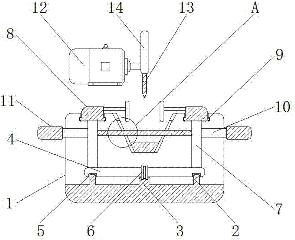
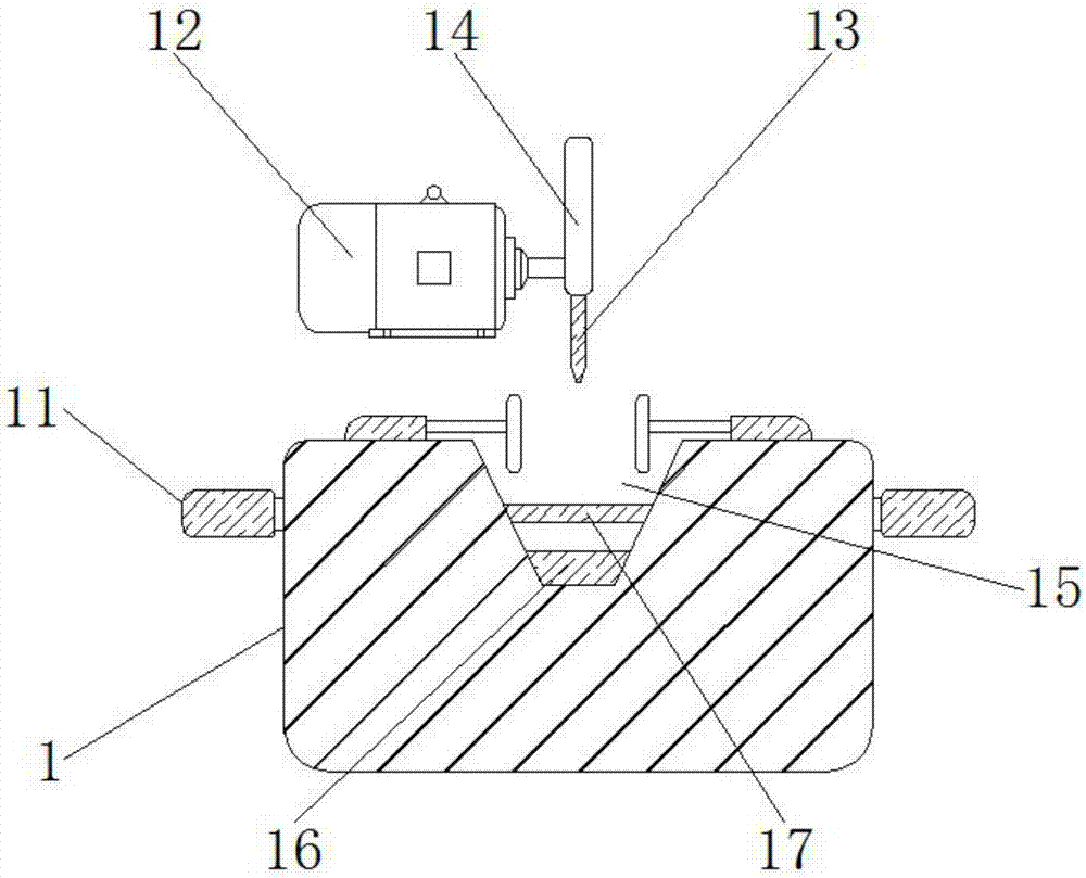
[0030] see Figure 1-6 , the present invention provides a technical solution: a mechanical traction cutting equipment, including a base 1, a drive motor 12 and a placement plate 17, the inside of the base 1 is provided with a bump 2, and the bump 2 passes through the groove 5 and the cross bar 4 The horizontal bar 4 is installed parallel to the inner lower surface of the base 1, and the horizontal bar 4 is connected with the vertical bar 7 by welding, which ca...


PUM


Abstract

The invention discloses mechanical traction cutting equipment which comprises a base, a driving motor and a placing plate. Bumps are arranged in the base and connected with a transverse rod through grooves. The outer surface of the transverse rod is nested with a sliding wheel, and the lower end of the sliding wheel is connected with a sliding rail. The upper ends of vertical rods are connected with clamping devices, and the clamping devices are installed inside sliding grooves. Both the left end and the right end of the placing plate penetrate through a movable groove to be connected with a connection rod. The outer end of the connection rod is nested with a connection rod sleeve. The upper end and the lower end of the placing plate are connected with pressing blocks correspondingly. The tail ends of the pressing blocks are connected with fixing blocks through compression springs. According to the mechanical traction cutting equipment, by the adoption of the design of the transverse rod, the bumps, the sliding rail, the grooves, the sliding wheel, the vertical rods, the placing plate, the movable groove, a transverse groove, an electrostatic dust collector, the pressing blocks and the fixing blocks, the cutting quality of a cut part can be ensured, the cutting depth of the cut part can be changed, and the body health of workers can be ensured.

Description

technical field [0001] The invention relates to the technical field of traction cutting equipment, in particular to a mechanical traction cutting equipment. Background technique [0002] Among various cutting methods, in-line cutting is the most common cutting process. In order to ensure the quality of in-line cutting, a special traction device for cutting has been invented to push the cutting piece to the cutting blade, so that Cut it with a cutting blade. [0003] The existing traction cutting equipment is easy to produce cutting dust when cutting the cutting parts, causing environmental pollution, and is not conducive to the health of workers. The upper surface of the base is provided with a dust collection groove to collect the dust generated during cutting, but there are still shortcomings. Because it only fixes the cutting part through the workpiece clamping part, it is easy to make the cutting part when the cutting blade contacts the cutting part. Downward displacem...

Claims


Application Information

Patent Timeline
IPC IPC(8): B24B27/06B24B41/06B24B55/06
CPCB24B27/06B24B41/06B24B55/06
Inventor 沈抗勇宗寒胡鉴涛
Owner 池州市勇攀智岩机电有限公司
Why Eureka
Try Eureka