Fluoroplastic extrusion equipment

A technology of extrusion equipment and fluoroplastics, which is applied in the field of wire and cable manufacturing, can solve the problems of low efficiency of extrusion equipment, limited extrusion performance, and affecting the quality of extrusion insulation, so as to ensure the quality of extrusion insulation and avoid residence time Excessive length, the effect of relieving thermal cross-linking phenomenon

Inactive Publication Date: 2017-09-22
ANHUI PACIFIC CABLE CO LTD
View PDF2 Cites 1 Cited by
  • Summary
  • Abstract
  • Description
  • Claims
  • Application Information

AI Technical Summary

Problems solved by technology

[0003] In recent years, with the development of technology, a new material XETFE (cross-linked ethylene-tetrafluoroethylene copolymer or cross-linked F40) has been used in aviation for its high temperature resistance, good mechanical properties, aging resistance, and chemical solvent resistance. The aerospace cable industry is widely used, but due to the limitations of the extrusion performance of XETFE materials, ordinary high-temperature extruders cannot meet its processing requirements, so the product is currently mainly dependent on imports, and the price is expensive
Through the research on XETFE materials, we found that XETFE materials are made of pure ETFE resin plus other components, and completely change the melting and flow of ETFE. XETFE in the extrusion barrel is prone to thermal crosslinking and degradation to varying degrees. As a result, the quality of extrusion insulation is affected, and the existing fluoroplastic extrusion equipment cannot take into account the production process of ordinary fluoroplastics and XETFE materials at the same time, which not only makes the use efficiency of extrusion equipment low, but also the investment cost of equipment is high

Method used


Image

  • Fluoroplastic extrusion equipment
  • Fluoroplastic extrusion equipment
  • Fluoroplastic extrusion equipment

Examples


Embodiment Construction

[0021] The following is attached Figures 1 to 4 Examples of the present invention are given to further illustrate the specific implementation of the fluoroplastic extrusion equipment of the present invention. The fluoroplastic extrusion equipment of the present invention is not limited to the description of the following examples.

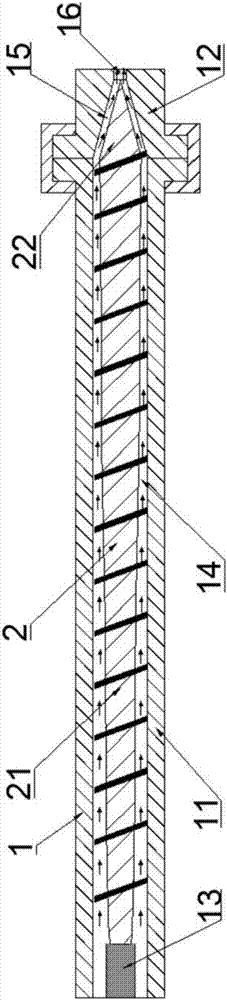
[0022] Such as figure 1 As shown, the fluoroplastic extrusion equipment of the present invention includes an extruder 1, and a cavity is provided inside the extruder 1, and the cavity includes a connected fuselage cavity 14 and a head cavity 15 for The first screw rod 2 extruding the XETFE material is rotatably installed in the cavity and arranged opposite to the extrusion hole 16 of the extruder 1. The first screw rod 2 includes a rod body 21 and a head 22 connected end to end, so The rod body 21 and the head 22 are located in the fuselage cavity 14 and the head cavity 15 respectively so as to form a streamlined channel without dead ends, so th...


PUM

PropertyMeasurementUnit
angleaaaaaaaaaa
tensile strengthaaaaaaaaaa

Abstract

Fluoroplastic extrusion equipment comprises an extruder. A cavity is formed in the extruder. The cavity comprises a machine body cavity and a machine head cavity which are in communication. A first screw is arranged in the cavity and is opposite to an extrusion hole of the extruder. The first screw comprises a rod body and a head part which are connected in an end-to-end manner. The rod body and the head part are located in the machine body cavity and the machine head cavity correspondingly so as to form a dead-angle-free streamline channel. The machine head cavity of the extruder is in a conical shape, the head part of the first screw is also in a conical shape, and the angle of the taper angle of the head part of the first screw is matched with the angle of the taper angle of the machine head cavity. According to the fluoroplastic extrusion equipment, the head part of the first screw directly stretches into the machine head cavity, and accordingly the staying time of XETFE fusion bodies in the machine head cavity is prevented from being too long; and through the dead-angle-free streamline channel, the extrusion insulation quality of the XETFE material can be guaranteed.

Description

technical field [0001] The invention relates to the field of wire and cable manufacturing, in particular to fluoroplastic extrusion equipment. Background technique [0002] Fluoroplastics are often used as insulating materials in existing cable structures. Common fluoroplastics include FEP (polyfluoroethylene propylene FEP or F46), PFA (soluble polytetrafluoroethylene) and ETFE (ethylene-tetrafluoroethylene copolymer or F40) and so on. [0003] In recent years, with the development of technology, a new material XETFE (cross-linked ethylene-tetrafluoroethylene copolymer or cross-linked F40) has been used in aviation for its high temperature resistance, good mechanical properties, aging resistance, and chemical solvent resistance. The aerospace cable industry is widely used, but due to the limitations of the extrusion performance of XETFE materials, ordinary high-temperature extruders cannot meet its processing requirements, so the product is currently mainly dependent on imp...

Claims


Application Information

Patent Timeline
Patent Type & Authority Applications(China)
IPC IPC(8): B29C47/38B29C47/60B29C48/395
CPCB29C48/397B29C48/505B29C48/625
Inventor 范涛崔海洋田鸣惠俊恒高兴
Owner ANHUI PACIFIC CABLE CO LTD
Why Eureka
Try Eureka