Method for reducing deformation of U-shaped composite part

A composite material and U-shaped technology, which is applied in the field of composite material processing, can solve the problems of reduced surface accuracy, long cycle and high development cost, and achieve the effect of reducing deformation of parts and ensuring surface accuracy.

Active Publication Date: 2017-09-22
BEIJING AUTOMOTIVE IND CORP +1
View PDF6 Cites 1 Cited by
  • Summary
  • Abstract
  • Description
  • Claims
  • Application Information

AI Technical Summary

Problems solved by technology

This method is basically completely based on the experience of the processing personnel, and the degree of mold repair cannot be grasped quantitatively and accurately, and the surface accuracy is seriously reduced. Generally, repeated rounds of trial and error are required to repair the mold. The development cost is very high and the cycle is also long.

Method used


Image

  • Method for reducing deformation of U-shaped composite part
  • Method for reducing deformation of U-shaped composite part
  • Method for reducing deformation of U-shaped composite part

Examples


Embodiment 1

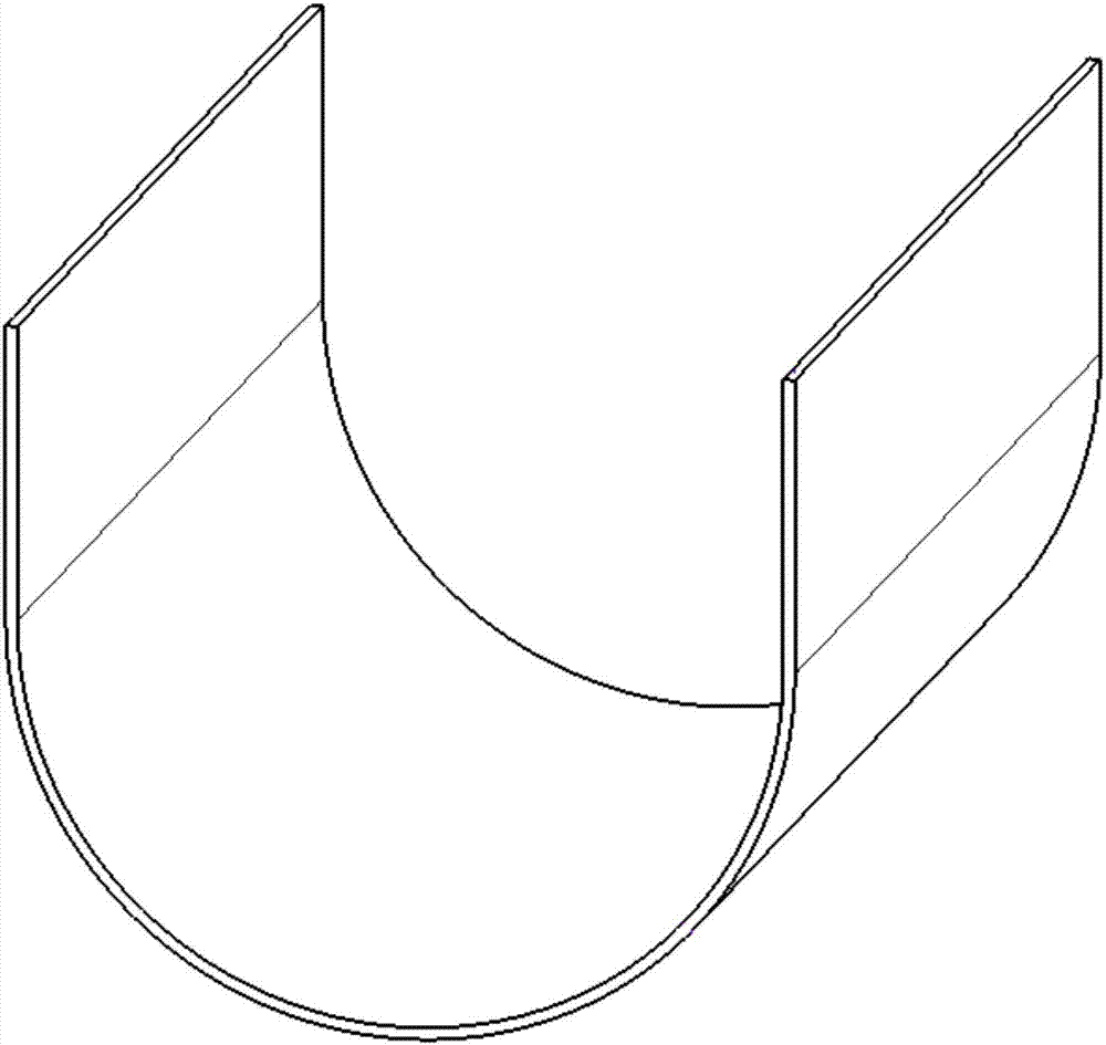
[0057] The U-shaped part that present embodiment makes is as figure 1 shown. The U-shaped opening of the target workpiece requires dimension K 0 for First, use T300-3K unidirectional epoxy prepreg (purchased from Shandong Guangwei Company, made of Toray Company T300 continuous carbon fiber), according to [0° 2 / 90° / 0° / +45° / -45° / 0° 2 / 90° / 0°] s The original lay-up design is placed in a metal counter-mold, molded under a pressure of 15MPa, and the curing temperature is about 120°C to produce a continuous fiber sample. Use a vernier caliper with an accuracy of 0.02mm to measure the U-shaped opening of the continuous fiber sample Size K 1 It is 195.98mm. Then replace all the orthogonal plies in the original ply design with 8 / 3 satin prepreg (purchased from Shandong Guangwei Company), that is, according to [0° / 90° 缎纹 / 0° / +45° / -45° / 0° / 90° 缎纹 / 0°] s The fiber is laid and the side of the satin fabric with less bending is facing the inside of the U-shaped structure. The satin...

Embodiment 2

[0059] The U-shaped part that present embodiment makes is as figure 1 shown. The U-shaped opening of the target workpiece requires dimension K 0 for First, use T300-3K unidirectional epoxy prepreg (purchased from Shandong Guangwei Company, made of Toray Company T300 continuous carbon fiber), according to [0° 2 / (90° / 0°) 3 / +45° / -45° / (0° / 90°) 2 / 0°] sThe original lay-up design was placed in a metal counter-mold, molded under a pressure of 15MPa, and the curing temperature was about 120°C to produce a continuous fiber sample, and the U-shaped opening of the continuous fiber sample was measured with a vernier caliper with an accuracy of 0.02mm Size K 1 1 It is 291.90mm. Then replace all the orthogonal plies in the original ply design with 8 / 3 satin prepreg (purchased from Shandong Weihai Guangwei Company), that is, according to [0° / 90° 缎纹3 / 0° / +45° / -45° / 90° 缎纹2 / 0°] s The fiber is laid and the side of the satin fabric with less bending is facing the inside of the U-sh...


PUM


Abstract

The invention relates to a method for reducing deformation of a U-shaped composite part. The method comprises the following steps: a, making a continuous fiber sample part according to the layer lay-up design of a target part, and measuring the U-shaped opening dimension K1 of the continuous fiber sample part; b, making a satin fabric sample part after completely replacing the cross-ply layers in the layer lay-up design with satin fabric, and measuring the U-shaped opening dimension K2 of the satin fabric sample part; c, calculating the layer number Q of the satin fabric after correction; and d, making a U-shaped part after correction according to the rules that the number of the cross-ply layers of the satin fabric is Q and the number of the continuous fiber cross-ply layers is N-Q. According to the method for reducing deformation of the U-shaped composite part, the die surface can be obtained without long-time complicated and difficult calculation, making a new die after carrying out additional finite element calculation is not needed, and meanwhile repeated die repairing is also not needed.

Description

technical field [0001] The present disclosure relates to the field of composite material processing, and in particular, relates to a method for reducing deformation of composite U-shaped workpieces. Background technique [0002] Continuous fiber reinforced composite materials have been widely used in the aerospace field due to their high specific strength, large specific modulus, corrosion resistance, good fatigue resistance, and strong design freedom. metallic material. At present, the application level of composite materials has gradually become an important indicator for evaluating the advancement of aircraft and automobiles. [0003] However, when the composite material part undergoes high temperature solidification molding and cooling process, the chemical reaction shrinkage effect of the matrix resin, and there is a significant difference in the thermal expansion coefficient between the composite material and the metal mold material commonly used for molding, due to t...

Claims


Application Information

Patent Timeline
Patent Type & Authority Applications(China)
IPC IPC(8): B29C70/20
CPCB29C70/202
Inventor 刘永杰栗娜马治国
Owner BEIJING AUTOMOTIVE IND CORP
Why Eureka
Try Eureka