Underground drainage system with first water storage and last slow infiltration functions

A technology of seepage, drainage and ground, which is applied in the direction of waterway systems, drainage structures, sewage discharge, etc., can solve the problems of permeable pavement blockage, difficulty, and high maintenance costs, and achieve the effect of eradicating urban waterlogging

Inactive Publication Date: 2017-09-22
GUANGXI UNIV
View PDF5 Cites 5 Cited by
  • Summary
  • Abstract
  • Description
  • Claims
  • Application Information

AI Technical Summary

Problems solved by technology

In addition, the permeable pavement is easily blocked by sand, dust and other small particles, and the permeable pavement needs regular maintenance to maintain a high water permeability, which is costly and difficult to maintain
Thirdly, permeable pavement has relatively low strength and durability compared with traditional dense pavement, so permeable pavement can only be applied to low-traffic pavement (such as parking lots) rather than main streets in inner cities

Method used


Image

  • Underground drainage system with first water storage and last slow infiltration functions
  • Underground drainage system with first water storage and last slow infiltration functions
  • Underground drainage system with first water storage and last slow infiltration functions

Examples


Embodiment 1

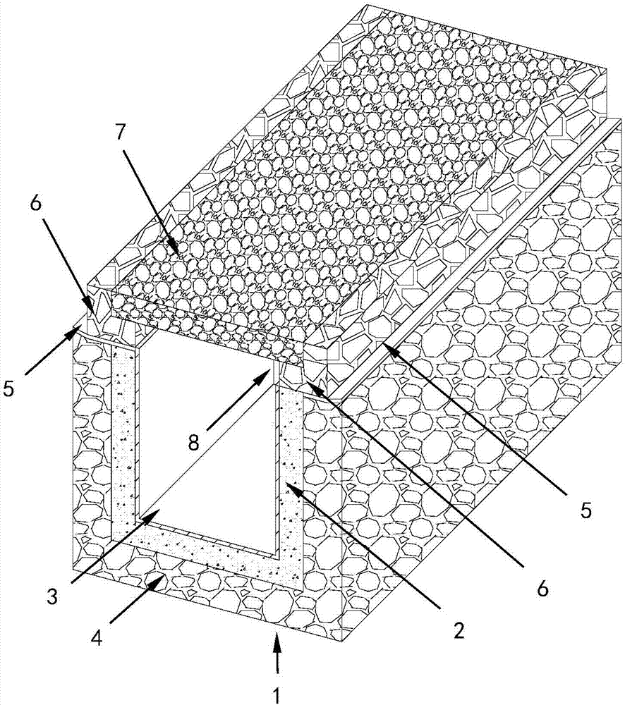
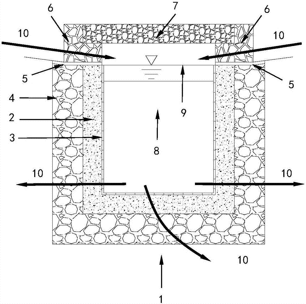
[0028] Such as Figure 1 to Figure 4 As shown, an example of the underground water storage and then slow seepage drainage system of the present invention is located at the bottom of low-load places such as residential quarters, parking lots, and parks. The application schematic diagram is as follows Figure 5 As shown, make full use of the bottom space of these places for rainwater regulation and storage. Among them, the reinforced top cover 7 covering the top of the slow seepage drainage structure 2 is used as the ground structure and is the main water inlet. A water-filtering filter material 3 is arranged inside the slow-seepage drainage structure 2 to allow only water to pass through and sand and soil to pass through. The slow seepage drainage structure 2 is one of three forms: bottom seepage, wall seepage, and bottom wall double seepage. The water permeability of the slow seepage structure should be 5-50 cm / day, preferably 5 cm / day. In order to make the water inside the ...

Embodiment 2

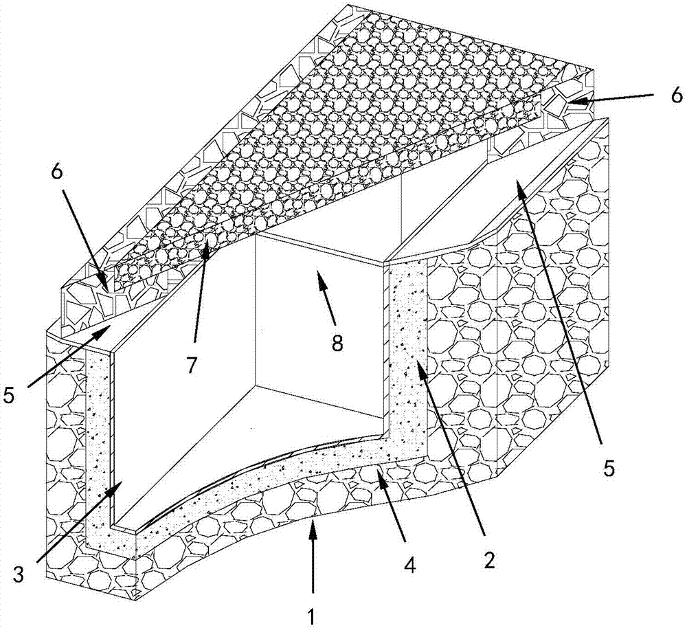
[0030] In this embodiment, on the side of urban roads or other linear projects, an underground water storage and then slow seepage drainage system is arranged to replace the traditional drainage ditches. The application schematic diagram is as follows Image 6 shown. A number of permeable curbstones 6 are arranged on the side of the slow seepage drainage structure 2 as water inlets, which are made of permeable materials with a water permeability of 0.1-5 cm / s. The opening distance, opening size, single-side or double-side opening of the water inlet can be determined according to the actual working conditions. Ground runoff enters the slow seepage drainage structure through the permeable curbstone 6 . The permeable and reinforced roof 7 on the top of the slow seepage drainage structure is used as sidewalks on both sides of urban roads, allowing rainwater or ground runoff to enter the slow seepage drainage structure 2 .

[0031] The reinforced permeable cover 7 is separated fr...

Embodiment 3

[0033] Such as figure 1 As shown, another application example of the underground water storage first and then slow seepage drainage system described in the present invention. The slow seepage drainage structure 2 prepared by using slow seepage concrete, the mix ratio of slow seepage concrete: 80-100 parts by weight of 4-9 mm aggregate, 46-58 parts by weight of 2-4 mm aggregate, 50 parts by weight of 1-2 mm aggregate -63 parts by weight, 24-30 parts by weight of fine powder less than 1 mm, 40-50 parts by weight of cement gelling material, and 17-21 parts by weight of water. Preferably: 90 parts by weight of aggregates of 4-9 mm, 52 parts by weight of aggregates of 2-4 mm, 56 parts by weight of aggregates of 1-2 mm, 27 parts by weight of fine powder less than 1 mm, 45 parts by weight of cement, and 19 parts by weight of water . The cement is 42.5 grade ordinary Portland cement, the slump of the concrete mixture is strictly controlled to be 0 cm, and the slow permeable concrete...


PUM


Abstract

The invention provides an underground drainage system with first water storage and last slow infiltration functions. The underground drainage system comprises a slow infiltration drainage structure with a filtering material, a reinforced top cover, a plurality of water permeation and water inlet openings and a plurality of separation plates. A specific structure is that the underground drainage system is provided with the filtering material which is laid in a slow infiltration drainage structure and is used for preventing suspension particles carried by surface runoff from entering a slow infiltration material; the underground drainage system is provided with the reinforced top cover at the upper part of the slow infiltration drainage structure and the reinforced top cover can be used as a side pavement, a parking lot or a ground activity place; the underground drainage system is provided with the water permeation and water inlet openings which are used for preventing large particles carried by the surface runoff from entering the slow infiltration material, and is provided with the separation plates which can be used for intercepting rainwater in the slow infiltration drainage structure and preventing the rainwater which is not slowly infiltrated and evacuated in situ from flowing into low-lying areas. By adopting the underground drainage system provided by the invention, the surface runoff can be intercepted in situ, and underground water is supplemented by in-situ slow infiltration; road surface gathered water formed by rainfall is reduced, and urban waterlogging is alleviated, so that the underground drainage system is a novel sponge body for effectively reducing the urban waterlogging.

Description

technical field [0001] The invention relates to the fields of sponge city, urban drainage and municipal engineering, in particular to an underground water storage first and then slow seepage drainage system. Background technique [0002] Inside cities, most of the surface soil and lawns are replaced by hard materials such as roofs, asphalt, concrete stone slabs or cement bricks. Due to the impermeability of such hard materials, rainwater cannot effectively penetrate into the underground soil layer, and the rainwater falling on the hard impermeable pavement forms ground runoff. When the surface runoff exceeds the drainage capacity of the urban sewer system, urban waterlogging is caused; at the same time, due to the rising groundwater level and the rapid collection of groundwater from high places to low places, the groundwater level at low places rises rapidly, and rainwater cannot pass through the underground drainage system in a timely and effective manner. Excluded to form...

Claims


Application Information

Patent Timeline
Patent Type & Authority Applications(China)
IPC IPC(8): E01C11/22E03F1/00E03F5/00
CPCE01C11/227E03F1/002E03F5/00Y02A20/40
Inventor 覃英宏龙相如陈夏渊贺玉辉
Owner GUANGXI UNIV
Why Eureka
Try Eureka