Resource joint optimization method for multi-target velocity estimation of distributed MIMO radar system

A radar system and speed estimation technology, applied in the field of MIMO radar, can solve problems such as different data transmission volume and computational complexity, limited transmission power, and affect task execution effect, so as to achieve good practical application value, improve tracking accuracy, and improve tracking performance effect

Active Publication Date: 2017-09-22
THE PLA INFORMATION ENG UNIV
View PDF5 Cites 11 Cited by
  • Summary
  • Abstract
  • Description
  • Claims
  • Application Information

AI Technical Summary

Problems solved by technology

Especially for airborne, vehicle-mounted and ship-borne radars, the transmission power of the system is usually limited. When the working time is long, the problem of resource shortage will be highlighted. At the same time, in the multi-task mode,

Method used


Image

  • Resource joint optimization method for multi-target velocity estimation of distributed MIMO radar system
  • Resource joint optimization method for multi-target velocity estimation of distributed MIMO radar system
  • Resource joint optimization method for multi-target velocity estimation of distributed MIMO radar system

Examples


Embodiment 2

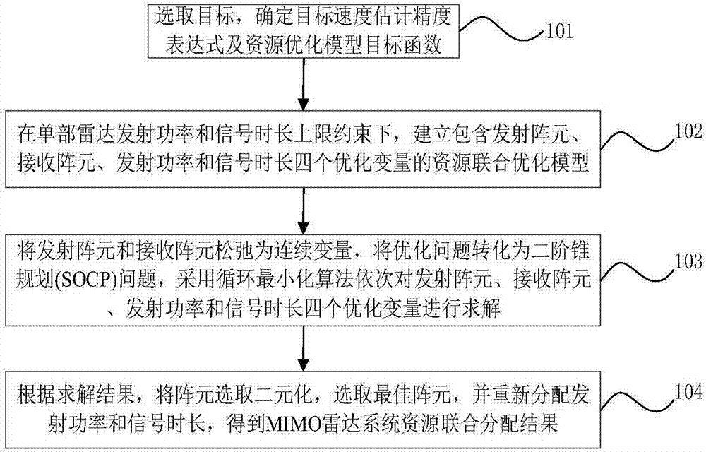
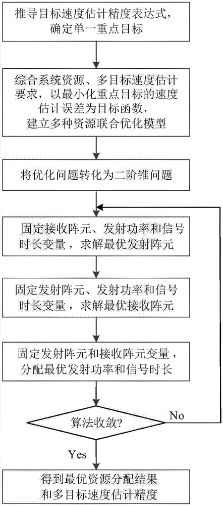
[0044] Embodiment two, see figure 2 As shown, a resource joint allocation method for multi-target velocity estimation in a distributed MIMO radar system specifically includes the following steps:

[0045] Step 1: Select a key target q * , calculate the target speed estimation accuracy expression, and use it as the objective function of the resource optimization model.

[0046] The distributed MIMO radar system contains M transmitting radars and N receiving radars. The radar interval is large enough to track Q moving targets. In a two-dimensional plane, the coordinates of the transmitting radar are The receiving radar coordinates are The target position state is (x q ,y q ),q=1,...Q, the speed state is Assume that each radar transmits an orthogonal signal s m (t), m=1,...M, satisfy T m is the signal duration, τ 0 for the signal delay. Define the transmit power vector of the radar as p=[p 1 ,p 2 ,...,p M ] T , the signal duration vector is t=[t 1 ,t 2 ,.....

Embodiment 3

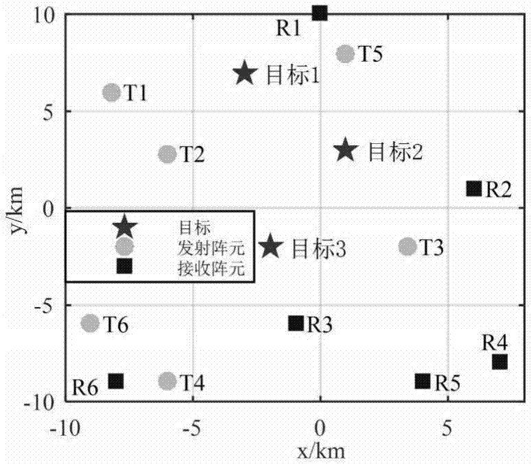
[0096] 1) Simulation conditions:

[0097] Considering the distributed MIMO radar platform with M=6, N=6, in the experimental scene of 20×20km, the velocity estimation of Q=3 moving targets is analyzed. The maximum number of transmitting and receiving array elements allowed to be selected by the radar system is Kt=4, Kr=4 respectively. The total transmission power of the system is P total =6kw, the upper limit of the transmitting power of a single radar is p max =4kw, the total duration of the signal is T total = 0.6s, the upper limit of the signal transmission time of a single radar is t max = 0.4s. Assuming that target 1 is always the key target in the objective function, MSE is the speed estimation requirement of the system for target 2 and target 3. In this paper, four resource allocation algorithms are considered to estimate the target speed, which are the selection of transceiver elements, the joint allocation of array element selection and transmit power, the joint ...


PUM


Abstract

The invention relates to a resource joint optimization method for the multi-target velocity estimation of a distributed MIMO radar system. The method comprises the following steps that: a target is designated, with minimizing key target velocity estimation error as an objective function, a resource joint optimization model including transmitting array elements, receiving array elements, transmitting power and signal time length is established; an optimization problem is transformed into a second-order cone programming problem, a cyclic minimization algorithm is adopted to solve four optimization variables sequentially; and after the algorithm converges, circulation is terminated, array element selection variables are dualized, an optimal array element is selected, transmitting power and signal time length are re-allocated, so that the result of resource joint allocation is obtained. The method of the invention has high flexibility for the number of tracking targets. With the method adopted, fewest transmitting array elements can be selected under a condition that the requirements of different speed estimation of a plurality of targets are satisfied, key target tracking performance can be improved, and multi-target overall tracking accuracy error is minimum. The method has a high application value.

Description

technical field [0001] The invention belongs to the technical field of MIMO radar, in particular to a resource joint optimization method for multi-target velocity estimation in a distributed MIMO radar system. Background technique [0002] Distributed MIMO radar has a large distance between transceiver elements and good space diversity gain, which has the advantage of overcoming target RCS scintillation. However, as radar functions become more and more perfect, the resource management of radar systems has gradually become an important part of military applications. Especially for airborne, vehicle-mounted and ship-borne radars, the transmission power of the system is usually limited. When the working time is long, the problem of resource shortage will be highlighted. At the same time, in the multi-task mode, resource scheduling and signal bandwidth and time under different tasks The distribution of all will affect the effect of task execution, and bring different data trans...

Claims


Application Information

Patent Timeline
IPC IPC(8): G01S7/02
CPCG01S7/02
Inventor 郑娜娥宋喜玉任修坤陈松吕品品田英华柏婷张龙张靖志
Owner THE PLA INFORMATION ENG UNIV
Why Eureka
Try Eureka