
Novel mixing machine dust collection device

A technology of dust collection device and mixer, which is applied in the direction of mixer, mixer accessories, transportation and packaging, etc. It can solve the problems of uneven mixing, easy occurrence of clogging of casting machine and dust collection port, etc., achieves fast and uniform mixing, and avoids knots blocks, reducing the number of downtime for cleaning

Inactive Publication Date: 2017-09-26
BEIJING NEW BUILDING MATERIALS PLC
View PDF3 Cites 3 Cited by
  • Summary
  • Abstract
  • Description
  • Claims
  • Application Information

AI Technical Summary

Problems solved by technology

[0003] In view of the technical problem existing in the prior art that the internal pressure change of the mixer causes the injected slurry inside the dust collection port to accumulate into blocks and cause the dust collection port to be blocked as a whole, the purpose of the present invention is to provide a new type of dust collection device for the mixer, It can solve the problems of uneven mixing caused by the blockage of the dust collection port of the mixer, easy material leakage from the position of the stirring shaft, and easy occurrence of casting machines, etc.

Method used


Image

  • Novel mixing machine dust collection device
  • Novel mixing machine dust collection device
  • Novel mixing machine dust collection device

Examples


Embodiment 1

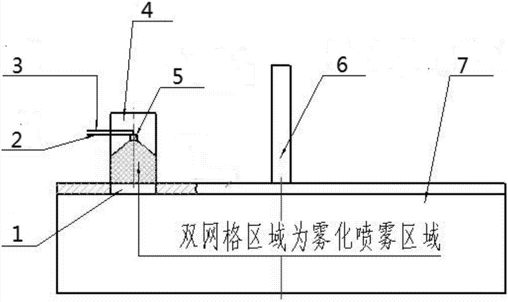
[0019] Such as figure 1 As shown, a new type of mixer dust collection device includes a mixer 7 and a dust collection device 4. The mixer 7 is connected to the motor through the mixer main shaft 6 arranged at the upper central axis, and the upper end surface of the mixer 7 is provided with a dust collector. hole 1, the dust collection device 4 is seamlessly connected with the dust collection hole 1 of the mixer 7, the dust collection device 4 includes a casing and a self-suction nozzle 5, and the self-suction nozzle 5 is installed in the upper middle of the casing, and the dust collection device 4 The upper end of the housing is provided with an air inlet and a water inlet, and the self-priming nozzle 5 communicates with the air inlet pipe 2 and the water inlet pipe 3 passing through the air inlet and the water inlet respectively.

[0020] The shell of the dust collecting device 4 is set as a hollow polytetrafluoroethylene tube, and the polytetrafluoroethylene tube is finely g...

Embodiment 2

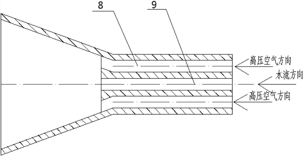
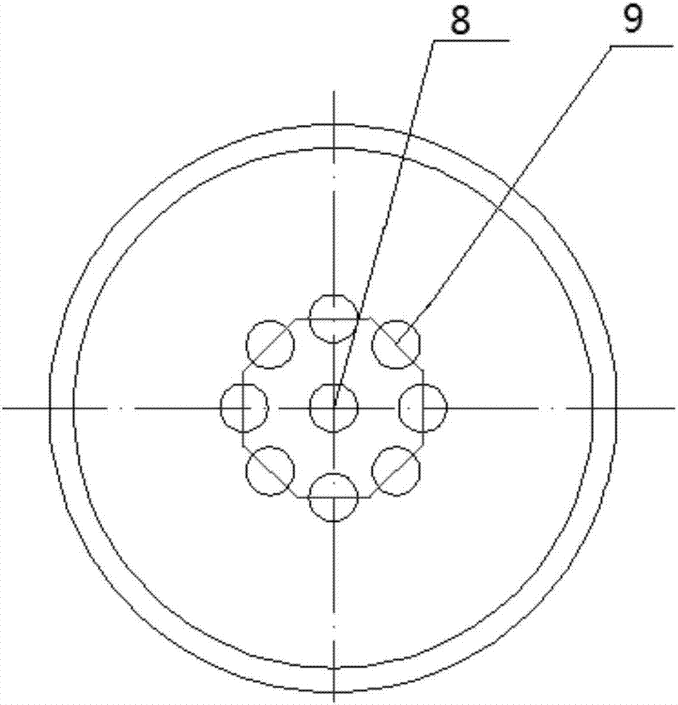
[0023] On the basis of Example 1, different from Example 1, such as figure 2 and image 3 As shown, a novel mixer dust collection device includes a self-priming nozzle 5, the self-priming nozzle 5 is set to an inverted funnel-shaped structure, and the center of the spray end of the self-priming nozzle 5 is provided with a water flow channel 8, so as to The water flow channel 8 is provided with an air flow channel 9 in a circular shape at the center of the circle, and the adjacent air flow channels 9 have the same diameter and are arranged at equal intervals. When the self-priming nozzle 5 is running, the high-pressure air enters the airflow channel 9 through the inlet pipe 2, and the water flow enters the water flow channel 8 through the water inlet pipe 3. At the same time, the airflow and water flow collide during the spraying process, which increases the atomization of the spray liquid. The degree, thereby increasing its contact area with the slurry, has the effect of uni...

Embodiment 3

[0025] On the basis of Example 1, different from Example 1, a new type of mixer dust collection device includes a self-priming nozzle 5, the upper end of which is set as a sawtooth-shaped disc around, self-priming The middle part of the spray head 5 is set as a hollow conical nozzle hole which successively decreases in step shape, and the lower end of the self-priming spray head 5 is set with a hollow spherical structure. The hollow sphere structure is beneficial to store liquid and provide a certain pressure for the spraying of liquid. The special structure of the nozzle hole makes the liquid spread outward along the stepped circular platform. As the flow channel of the water flow narrows progressively, the pressure of the water flow increases. , to facilitate the formation of water mist, and at the same time, prevent the slurry outside the self-priming nozzle 5 from flowing back into the nozzle to cause blockage, and improve the dust collection efficiency.


PUM


Abstract

The invention discloses a novel mixing machine dust collection device comprising a mixing machine and a dust collection device. The mixing machine is connected a motor through a mixing machine spindle arranged the upper center axis. A dust collecting hole is formed in the upper end face of the mixing machine. The dust collection device is connected with the dust collection hole of the mixing machine in seamless and butting modes and comprises a shell and a self-suction nozzle. The self-suction nozzle is installed on the middle-upper portion inside the shell. An air inlet and a water inlet are formed in the upper end of the shell of the dust collection device. The self-suction nozzle communicates with an air inlet pipe and a water inlet pipe which penetrate through the air inlet and the water inlet correspondingly. The sealing performance of the dust collection hole and the dust collection device is good. Liquid entering the nozzle through the air inlet pipe and the water inlet pipe is atomized through the nozzle, and slurry on the inner wall of the dust collection device is uniformly flushed away, the caking problem of the dust collection hole is avoided, the situation that the a dust collection opening is in a non-clogging state all the time can be guaranteed, and the time of shutdown for cleaning is decreased. According to the novel mixing machine dust collection device, pressure balance of the mixing machine to the atmosphere can be guaranteed all the time, stirring uniformity is achieved.

Description

technical field [0001] The invention belongs to the technical field of gypsum board production, and in particular relates to a novel mixer dust collecting device. Background technique [0002] Most of the existing dust collection ports are dust collection ports with a water ring structure. During the continuous production process of this structure, due to the change in the internal pressure of the mixer, the injected slurry inside the dust collection port accumulates into blocks, resulting in blockage of the water ring, and further The overall blockage of the dust collection port is caused. After the dust collection port is completely blocked, the pressure inside the mixer cannot be released, which will cause uneven mixing of water and gypsum, resulting in poor bonding of the plates, and the slurry will overflow from the position of the stirring shaft due to the imbalance between the internal pressure and the atmospheric pressure. As a result, there will be material leakage...

Claims


Application Information

Patent Timeline
Patent Type & Authority Applications(China)
IPC IPC(8): B08B3/02B08B13/00B01F15/00
CPCB08B3/02B08B13/00B01F35/1453
Inventor 梁云飞刘晨刘伟周继明郭臣明向清昌王浩然
Owner BEIJING NEW BUILDING MATERIALS PLC
Learn More