Tailing pond online monitoring system

A monitoring system and a technology for tailings ponds, which are applied in the field of online monitoring, can solve the problems of difficulty in grasping various technical indicators of tailings ponds in a timely manner, affecting safe production and safety management of tailings ponds, and inability to monitor technical parameters of tailings ponds in real time. , to achieve the effect of improving the ability to deal with harsh working environments, improving real-time monitoring capabilities, and improving monitoring accuracy

Inactive Publication Date: 2017-09-26
ANHUI GUANGAN ELECTRONICS TECH
View PDF5 Cites 1 Cited by
  • Summary
  • Abstract
  • Description
  • Claims
  • Application Information

AI Technical Summary

Problems solved by technology

The tailings pond is a dangerous source of man-made debris flow with high potential energy, and there is a danger of dam failure. Once the accident occurs, it is easy to cause serious accidents
[0003] At present, the safety monitoring of tailings ponds in my country is mostly carried out manually on-site with traditional instruments on a regular basis. The monitoring workload is heavy, and it is affected by many factors such as weather, labor, and site conditions. There are system errors and manual errors at one end. At the same time, manual monitoring There are also shortcomings such as the inability to monitor various technical parameters of the tailings pond operation in real time, and the difficulty in grasping various technical indicators of the safe operation of the tailings pond in a timely manner. These will affect the safe production and safety management of the tailings pond. Some projects have begun to use online monitoring to solve the problems caused by manual monitoring, but there are still many defects such as low monitoring accuracy and high equipment cost.

Method used


Image

  • Tailing pond online monitoring system
  • Tailing pond online monitoring system

Examples


Embodiment Construction

[0016] In order to make the technical means realized by the present invention; creative features; achieve the purpose and effect easy to understand, the present invention will be further elaborated below in conjunction with specific embodiments.

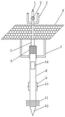
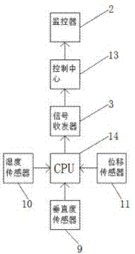
[0017] like Figure 1-2 As shown, an online monitoring system for tailings storage includes a fuselage 8, the top of the fuselage 8 is fixedly connected with a motor 6 by bolts, and the top of the motor 6 is rotatably connected with a transmission shaft 5, and the transmission shaft 5 A lightning arrester 1 is fixedly connected to the top of the lightning arrester 1, a monitor 2 is sleeved in the middle of the lightning arrester 1, a signal transceiver 3 is welded on both sides of the middle of the lightning arrester 1, and a signal transceiver 3 is welded on both sides of the middle of the lightning arrester 1, and the two sides of the top of the fuselage 8 are fixedly connected by bolts. A bracket 7, the top of the bracket 7 is fix...


PUM


Abstract

The present invention discloses a tailing pond online monitoring system. The system comprises a machine body, the top end of the machine body is fixedly connected with a motor through a bolt, the top end of the motor is rotationally connected with a transmission shaft, the top end of the transmission shaft is fixedly connected with a lightning arrester, the middle portion of the lightning arrester is sleeved with a monitor, and two sides of the middle portion of the lightning arrester are welded with signal transceivers. The design is reasonable, the usage is convenient, a solar cell is arranged to reduce the dependence on a traditional power supply, solve the defect that a tailing pond cannot be monitored when major disasters happen and improve the capacity of a device for response to a severe work environment, an inclination angle sensor is arranged to improve the monitoring precision, the monitor is arranged to improve the real-time monitoring capacity of the field environment, the lightning arrester is arranged to reduce the damaging of thunderstorm weather for the device and improve the device safety and the service life, and therefore, the tailing pond online monitoring system is simple and convenient and low in cost and is suitable for wide popularization.

Description

【Technical field】 [0001] The invention relates to the technical field of on-line monitoring, in particular to an on-line monitoring system for tailings pools. 【Background technique】 [0002] Tailings pool refers to the place where dams are built to intercept valley mouths or enclosures, and are used to stockpile metal or non-metal mines for ore sorting and then discharge tailings or other industrial waste. The tailings pond is a high potential energy man-made debris flow hazard, and there is a danger of dam failure. Once the accident occurs, it is easy to cause serious accidents. [0003] At present, the safety monitoring of tailings ponds in my country is mostly carried out manually on-site with traditional instruments on a regular basis. The monitoring workload is heavy, and it is affected by many factors such as weather, labor, and site conditions. There are system errors and manual errors at one end. At the same time, manual monitoring There are also shortcomings such as...

Claims


Application Information

Patent Timeline
Patent Type & Authority Applications(China)
IPC IPC(8): G01D21/02H02J7/35
CPCG01D21/02H02J7/35
Inventor 朱兵保夏娜
Owner ANHUI GUANGAN ELECTRONICS TECH
Why Eureka
Try Eureka