
Touch display panel and liquid crystal display equipment

A touch display panel, liquid crystal display technology, applied in printed circuits, instruments, electrical digital data processing, etc., can solve the problems of high manufacturing process cost, damage to chip on film, poor thermal conductivity of flexible circuit boards, etc.

Active Publication Date: 2017-09-26
BOE TECH GRP CO LTD +1
View PDF6 Cites 4 Cited by
  • Summary
  • Abstract
  • Description
  • Claims
  • Application Information

AI Technical Summary

Problems solved by technology

[0003] In order to realize the simultaneous binding of chip-on film and flexible circuit board, it is required that the manufacturing process, thickness and width of chip-on film and flexible circuit board are correspondingly the same (the manufacturing process of conventional flexible circuit board is different from that of chip-on film. Similarly, when bonding is carried out according to the current mass production process specifications, the thermal conductivity of the chip-on-chip film is high, and the conductive adhesive of the first conductive connection layer can be fully dissolved after absorbing heat during bonding, and the adhesive force of the first conductive connection layer can be It meets the design requirements; however, under this process condition, the thermal conductivity of the flexible circuit board is poor, and the conductive adhesive of the second conductive connection layer does not absorb enough heat to fully dissolve during binding, resulting in the failure of the adhesive force of the second conductive connection layer. Meet the design requirements; if the binding process is adjusted according to the design requirements of the flexible circuit board according to the design requirements of the tear-off force ≥ 1000N, the chip-on-chip film will be damaged due to excessive heat absorption, which means that the chip-on-chip film and flexible circuit The manufacturing process, thickness and width of the board correspond to the same reason), so that the thermal conductivity of the chip-on-film and the flexible circuit board are the same during bonding, and can be firmly adhered to the circuit board
[0004] Among them, the manufacturing process of the chip-on-chip film cannot be changed, so that the manufacturing process of the flexible circuit board can only be selected from the same manufacturing process as the chip-on-film film to make the flexible circuit board. Due to the high cost of the chip-on-film manufacturing process, This greatly increases the production cost of flexible circuit boards, which is contrary to the design idea of ​​enterprise product optimization.

Method used


Image

  • Touch display panel and liquid crystal display equipment
  • Touch display panel and liquid crystal display equipment
  • Touch display panel and liquid crystal display equipment

Examples


Embodiment Construction

[0026] In order to make the purpose, technical solutions and advantages of this document clearer, the embodiments of this document will be described in detail below in conjunction with the accompanying drawings. It should be noted that, in the case of no conflict, the embodiments in the present application and the features in the embodiments can be combined arbitrarily with each other.

[0027] In the following description, a lot of specific details are set forth in order to fully understand this article, but this article can also be implemented in other ways than described here, therefore, the protection scope of this article is not limited by the specific embodiments disclosed below .

[0028] The touch display panel and liquid crystal display device of some embodiments herein will be described below with reference to the accompanying drawings.

[0029] like Figure 4 As shown, the touch display panel provided herein includes: a substrate 1; a chip-on-chip film 2 (such as ...


PUM


Abstract

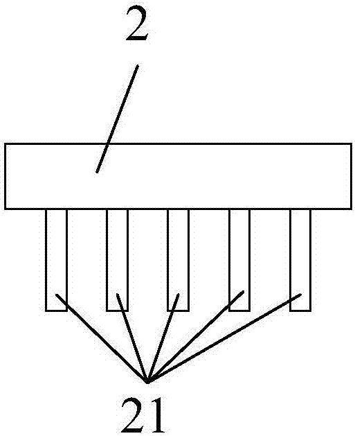
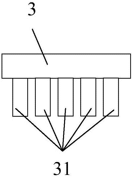
The invention discloses a touch display panel and liquid crystal display equipment. The touch display panel comprises a substrate, a chip on film and a flexible circuit board. One end of the chip on film is bound to the substrate, and the other end of the chip on film is provided with first binding pins. One end of the flexible circuit board is bound to the substrate, the other end of the flexible circuit board is provided with second binding pins, and the width L2 of the second binding pins is larger than the width L1 of the first binding pins. When a selected flexible circuit board manufacturing process is different from a chip on film manufacturing process, heat conductivity of the second binding pins is weaker than that of the first binding pins, the width of the second binding pins is increased and larger than that of the first binding pins, and thus, in simultaneous binding on a circuit board, within same binding time, heat storage quantity of the second binding pins is increased while a binding state of the first binding pins is unchanged, and a second conductive connection layer is further melted by excessive heat on the second binding pins after binding is finished, so that an adhesion effect identical to that of a first conductive connection layer is achieved.

Description

technical field [0001] This article relates to the field of panel technology, especially a touch display panel and a liquid crystal display device. Background technique [0002] In the process of making a touch display panel, in order to reduce the bonding time and improve production efficiency, it is usually chosen to simultaneously press the chip-on-chip film and the flexible circuit board on the circuit board through the same cutter head (ie: simultaneous bonding) to Bond the first binding pins of the COF to the first binding area of ​​the circuit board through the first conductive connection layer, and adhere the second binding pins of the flexible circuit board to the first binding area of ​​the circuit board through the second conductive connection layer. on the second bonding area of ​​the circuit board. [0003] In order to realize the simultaneous binding of chip-on film and flexible circuit board, it is required that the manufacturing process, thickness and width ...

Claims


Application Information

Patent Timeline
Patent Type & Authority Applications(China)
IPC IPC(8): G02F1/1345G02F1/1333G06F3/041
CPCG02F1/13338G02F1/13452G06F3/041G06F3/04164H05K3/323H05K3/361H05K2201/10128G06F2203/04103H05K1/028H05K1/036H05K2201/0154
Inventor 党康鹏左丞侯帅
Owner BOE TECH GRP CO LTD
Learn More