Soft switching flyback converter

A converter and transformer technology, applied in the field of soft switching and synchronous rectification flyback converters, can solve the problems of increasing the size of the switch, inability to cross, and increasing common mode electromagnetic interference.

Active Publication Date: 2017-09-26
TEXAS INSTR INC
View PDF12 Cites 6 Cited by
  • Summary
  • Abstract
  • Description
  • Claims
  • Application Information

AI Technical Summary

Problems solved by technology

However, the resonant voltage oscillation is not close to zero volts even at the valley, especially for high input voltage conditions
Therefore, true zero-voltage switching cannot be achieved across the wide range of operating conditions of conventional synchronous rectification flyback converters, and switching losses can be substantial
Therefore, under certain operating conditions, discontinuous mode (DM) switching operation must be used, which increases conduction losses and reduces converter ef...

Method used


Image

  • Soft switching flyback converter
  • Soft switching flyback converter
  • Soft switching flyback converter

Examples


Embodiment Construction

[0009] In the drawings, features are not necessarily drawn to scale. If a first device is coupled to or with a second device, that connection may be through a direct electrical connection or through an indirect electrical connection via one or more intervening devices and connections.

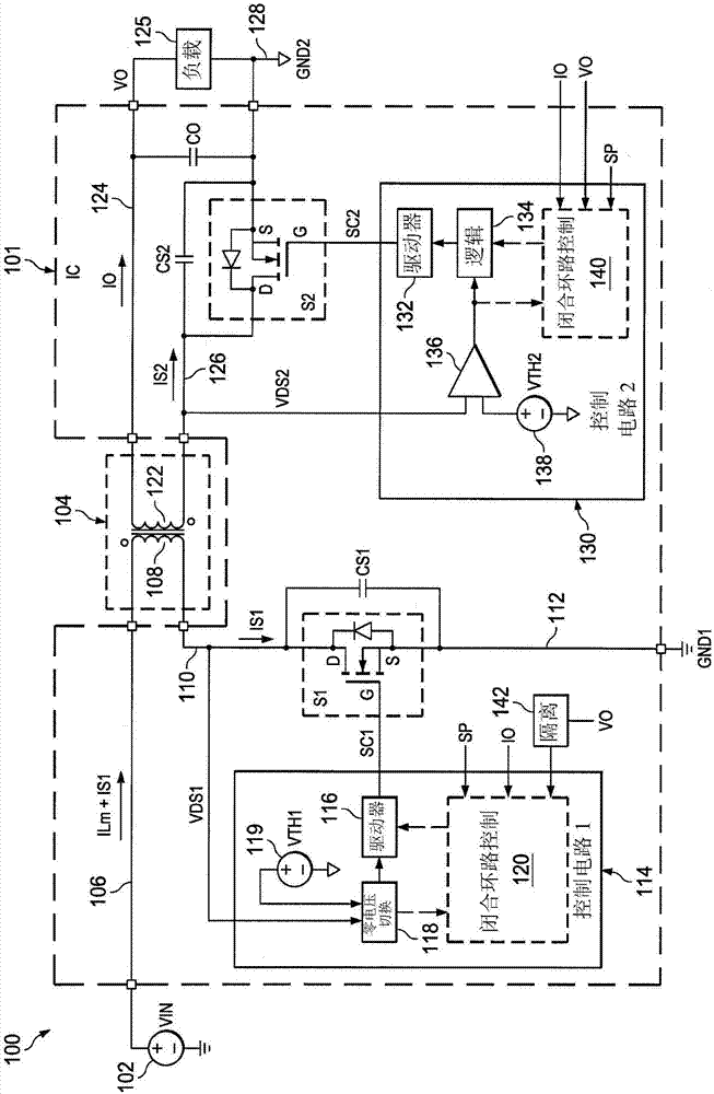
[0010] figure 1 A synchronous rectification flyback converter system 100 is shown comprising a transformer 104 to convert input power from a DC voltage source 102 to drive a load 125 , a primary side or first switch S1 and a secondary side or second switch S2 . The first switch S1 is operated by the first switching control signal SC1 provided by the first control circuit 114 , and the second switch S2 is operated according to the second switching control signal SC2 from the second control circuit 130 . In one example, switches S1 and S2 and control circuits 114 and 130 are provided in an integrated circuit (IC) 101 having terminals or pins or other suitable connections for receiving an input v...


PUM


Abstract

In described examples of synchronous rectifiers and flyback converters (100), integrated circuits (101) and operating methods, a first switch (S1) is turned on to allow current to flow for a first time period (Tl) in a first direction in a transformer primary winding (108) responsive to a first switch voltage (VDSl) transitioning below a first threshold (VTHl), and a second switch (S2) is turned on for a second time period (T2) after the first time period (Tl) to transfer energy from a secondary transformer winding (122) to drive a load (125). In the same converter cycle, the second switch (S2) is again turned on for a third time period (T3) in response to a second switch voltage (VDS2) transitioning below a second threshold (VTH2) at one of a series of troughs of a resonant ringing voltage waveform across the second switch (S2), to cause current flow in a second direction in the primary winding (108) to discharge a capacitance (CSl) of the first switch (SI) to cause the first switch voltage (VDSl) to transition below the first threshold (VTHl) to initiate a subsequent converter cycle.

Description

[0001] This relates generally to flyback converters, and more specifically to soft switching and synchronous rectification flyback converters. Background technique [0002] Synchronous rectifiers are used to perform DC-DC conversion to drive output loads, where transformers are often used to construct flyback converters with secondary side switches to provide efficiency advantages over passively rectified flyback converters. In many applications, efficiency is a primary design goal and it is desirable to reduce or mitigate switching and conduction losses in the primary and secondary side switches. Soft switching or zero voltage switching (ZVS) involves turning on the primary side switch and / or the secondary side switch when the voltage across the switches is low, preferably zero. Ideally, switching at zero volts minimizes switching losses, but this is difficult due to the drain-source capacitance of field effect transistor (FET) type switches. Conduction losses occur when the...

Claims


Application Information

Patent Timeline
IPC IPC(8): H02M3/335
CPCH02M3/33592H02M1/0058Y02B70/10H02M3/33507H02M3/33576
Inventor 艾萨克·科昂
Owner TEXAS INSTR INC
Why Eureka
Try Eureka