
Gripper structure

A technology of grippers and magnetic components, which is applied in the field of game equipment, can solve the problems of inability to replace grippers, increase manufacturing costs, and inconvenience in use, and achieve the effects of reducing the number of turns and usage, increasing the moving distance, and reducing manufacturing costs

Pending Publication Date: 2017-09-29
谢代英
View PDF9 Cites 6 Cited by
  • Summary
  • Abstract
  • Description
  • Claims
  • Application Information

AI Technical Summary

Problems solved by technology

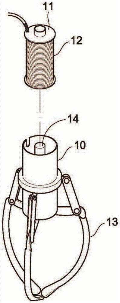
[0004] Because the above-mentioned gripper must wind a large amount of coils outside the valve pipe 11, the valve stem 14 of the gripper can be moved under the action of the magnetic field generated after the coil is energized, and then a large number of winding coils not only waste resources, but also increase the manufacturing cost. It is not possible to replace the claws of different sizes, which is also very inconvenient in use

Method used


Image

  • Gripper structure
  • Gripper structure
  • Gripper structure

Examples


Embodiment Construction

[0021] Below, the present invention will be further described in conjunction with the accompanying drawings and specific implementation methods. It should be noted that, under the premise of not conflicting, the various embodiments described below or the technical features can be combined arbitrarily to form new embodiments. .

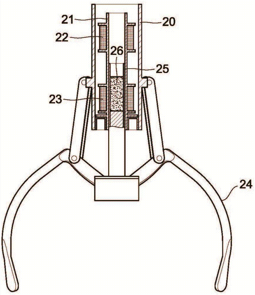
[0022] Such as figure 2 As shown, the gripper structure of the present invention includes a body 20, a valve tube 21 is arranged in the body 20, an upper coil segment 22 and a lower coil segment 23 are respectively wound around the upper and lower ends of the valve tube 21, and the upper coil segment 22 has a The end is connected with the starting end of the lower coil section 23, and the starting end of the upper coil section 22 is connected with the power supply device (not shown in the figure) with the end of the lower coil section 23. After the upper coil section 22 and the lower coil section 23 are energized , the upper coil segment 22 and the l...


PUM


Abstract

The invention discloses a gripper structure. The gripper structure comprises a body, a valve pipe, a clamping jaw and a vertical pipe, the valve pipe is arranged in the body, and the vertical pipe is pivoted to the clamping jaw which is pivoted to the bottom of the body. When the vertical pipe moves up and down, the clamping jaw is contracted inwards or expanded outwards, upper and lower ends of the valve pipe are wound by an upper coil section and a lower coil section respectively, the tail end of the upper coil section is connected with a starting end of the lower coil section, and a starting end of the upper coil section and the tail end of the lower coil section are connected with an external power source. The gripper structure further comprises a magnetic element which is arranged in the valve pipe in a vertically movable manner, and the magnetic element is connected with the vertical pipe. A magnetic pole at the top end of the magnetic element is opposite to that above the electrified upper coil section, a magnetic pole at the bottom end of the magnetic element is opposite to that above the electrified lower coil section, and the length of the magnetic element corresponds to a distance between the upper coil section and the lower coil section.

Description

technical field [0001] The invention relates to the field of game equipment, in particular to a claw structure. Background technique [0002] The object-grabbing game machine (or called a claw machine, a vending machine, etc.) is a kind of game machine that is widely loved by the public. [0003] The grasping claw of existing object grabbing game machine, such as figure 1 As shown, it includes a cylindrical body 10, a valve tube 11 is arranged inside the body 10, and a coil 12 is wound around the valve tube 11 to form a solenoid valve after being energized; the bottom of the body 10 is pivoted with a clip Claw 13, and this clamping claw 13 is pivotally connected with a valve rod 14, and this valve rod 14 is the metal bar member (such as: iron rod) that can be attracted by magnetic force, and this valve rod 14 extends in the valve tube 11; After the coil 12 of the valve tube 11 is energized, a magnetic force is generated, and the valve stem 4 is attracted by the magnetic fo...

Claims


Application Information

Patent Timeline
Patent Type & Authority Applications(China)
IPC IPC(8): A63F9/30
CPCA63F9/30
Inventor 林义河
Owner 谢代英
Learn More