Assembled coupling beam with built-in profiled steel sheet groove structure

A profiled steel plate and built-in profiled technology, applied to truss structures, joists, girders, etc., can solve problems such as insufficient shear bearing capacity of coupling beams, poor ductility, and increase the width of coupling beams to improve the shear-compression ratio Insufficient, improve the shear bearing capacity, reduce the effect of engineering

Active Publication Date: 2017-09-29
杭萧钢构(于都)有限公司
View PDF6 Cites 5 Cited by
  • Summary
  • Abstract
  • Description
  • Claims
  • Application Information

AI Technical Summary

Problems solved by technology

[0004] The object of the present invention is to propose an assembled coupling beam with a built-in profiled steel plate groove structure in view of the problems existing in the prior art. The profiled steel plate is arranged at the beam end to form a “groove structure” to ensure that the coupling beam and shear The strong connection between the force wall panels; increasing the width of the connecting beam and arranging corrugated steel plates can meet the structural requirements and facilitate installation, while effectively increasing the shear area of ​​the connecting beams, giving full play to the shear resistance and energy dissipation capabilities of the corrugated steel plates, and solving the problem of connecting beams. Insufficient shear bearing capacity and poor ductility of beams, etc., reduce the amount of formwork work on site, and facilitate the construction of single and multi-connected beam structures

Method used


Image

  • Assembled coupling beam with built-in profiled steel sheet groove structure
  • Assembled coupling beam with built-in profiled steel sheet groove structure
  • Assembled coupling beam with built-in profiled steel sheet groove structure

Examples


Embodiment

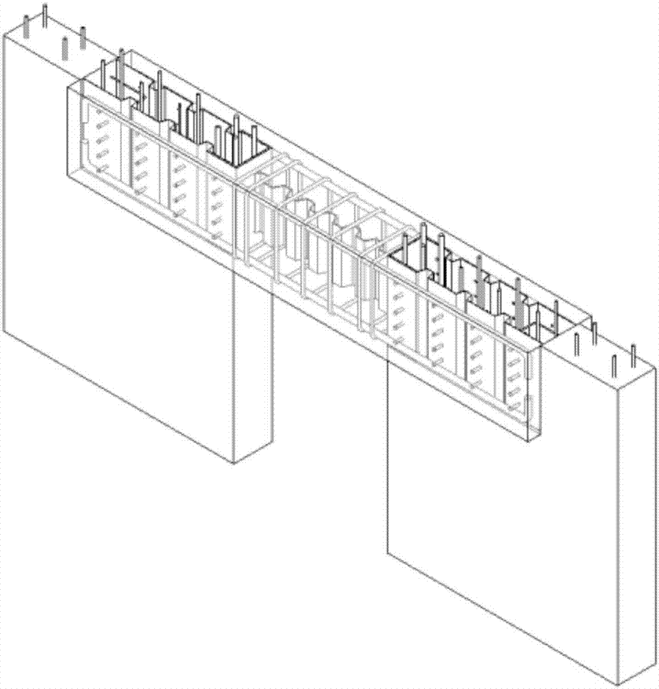
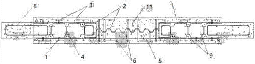
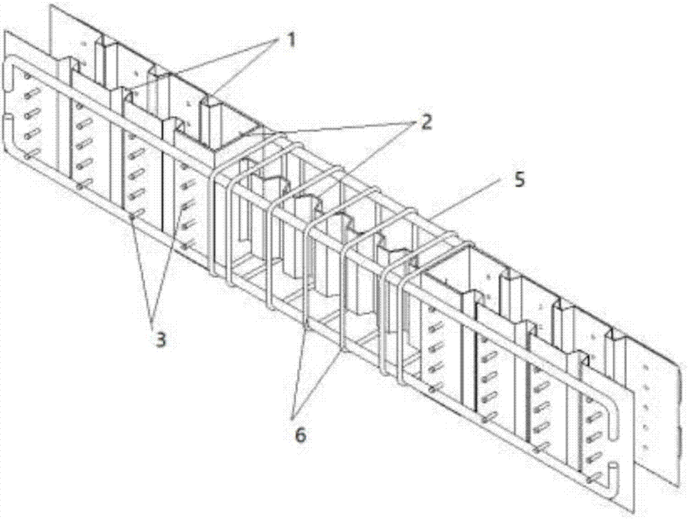
[0031] An assembled connecting beam with a built-in profiled steel plate groove structure includes a prefabricated shear wall panel and a prefabricated connecting beam. Among them, in addition to concrete, the prefabricated coupling beams also include coupling beam longitudinal ribs 5, coupling beam stirrups 6, profiled steel plates 1, profiled steel connecting rods 4, studs 3, and corrugated steel plates 2.

[0032] The length of the profiled steel plate shall not be less than the minimum anchorage length of the longitudinal reinforcement of the coupling beam. According to the thickness of the shear wall (spacing of structural steel bars), determine the spacing of the double-layer profiled steel plates, which should be greater than the spacing of the shear wall construction ribs. The double-layer profiled steel plates are fixed by connecting rods and are welded and supported near the surface of the beam. Weld studs according to structural requirements. The hoop formed by the pr...


PUM


Abstract

The invention discloses an assembled coupling beam with a built-in profiled steel sheet groove structure and belongs to the technical field of an assembled concrete structure. The assembled coupling beam consists of coupling beam longitudinal bars, coupling beam hooping bars, coupling beam concrete, corrugated steel plates, profiled steel sheets, profiled steel sheet connecting rods and toggle pins. Groove structures are formed at the two ends of a prefabricated coupling beam by arranging the profiled steel sheets with the toggle pins serving as inner formwork at the two ends of an assembled concrete prefabricated coupling beam component, a beam nest and the parts enclosed by grooves are cast in situ, and a detachable splicing system which is more simple and easy to construct is formed at a beam end, so that work quantity of field templates can be reduced, and construction difficulty is reduced. Cooperative work between the profiled steel sheets and the concrete can be ensured by the toggle pins arranged on the profiled steel sheet, strong connection between the coupling beam and a shear wall slab is realized through the profiled steel sheets and connecting components of the profiled steel sheets, wide coupling beam advantage is exerted, depth-span ratio is reduced while bending rigidity of the coupling beam is ensured, and the integrality and energy consumption ability of the structure are further improved.

Description

Technical field [0001] The invention belongs to the technical field of fabricated concrete structures, and specifically relates to an fabricated coupling beam with a built-in profiled steel plate groove structure. Background technique [0002] The connecting beam is an important component in the building structure. The shear wall connects the limbs together through the connecting beam, so that it is coordinated and deformed to form an overall lateral force-resistant structure. In the prefabricated concrete shear wall structure, the connecting beams are mainly constructed by the full cast-in-place construction method, or the method of lapping the fully prefabricated connecting beams on the reserved beam sockets of the shear wall and then casting in-situ To build, when the cast-in-place construction method is adopted, the amount of wet concrete work on the site will be very large; the work of supporting and dismantling the formwork in the construction of multiple beams or beams is ...

Claims


Application Information

Patent Timeline
Patent Type & Authority Applications(China)
IPC IPC(8): E04C3/22
CPCE04C3/22
Inventor 孙丽程章金峤张春巍
Owner 杭萧钢构(于都)有限公司
Why Eureka
Try Eureka