
Variable-diameter hydraulic cutter capable of realizing continuous cutting of sleevings with different diameters through gear and rack transmission

A rack-and-pinion and casing technology, which is applied in wellbore/well components, earthwork drilling, etc., can solve problems such as inability to accurately control the opening angle of the cutter body, low casing cutting efficiency, and easy wear and tear of the cutter, and achieve Improve the cutting efficiency, shorten the construction period, and prevent the effect of swarf winding around the blade

Inactive Publication Date: 2017-09-29
SOUTHWEST PETROLEUM UNIV
View PDF8 Cites 21 Cited by
  • Summary
  • Abstract
  • Description
  • Claims
  • Application Information

AI Technical Summary

Problems solved by technology

[0004] In order to solve the problems of low casing cutting efficiency in the process of well abandonment described in the background technology, the inability to accurately control the opening angle of the cutter body, the cutter is easy to wear, and the failure rate is high, and the continuous cutting operation of casings of different specifications is realized. , reduce the number of trips during the casing cutting process, improve the efficiency of well abandonment operations, and reduce costs and risks. The invention provides a variable-diameter hydraulic cutter that can continuously cut casings with different diameters through rack and pinion transmission.

Method used


Image

  • Variable-diameter hydraulic cutter capable of realizing continuous cutting of sleevings with different diameters through gear and rack transmission
  • Variable-diameter hydraulic cutter capable of realizing continuous cutting of sleevings with different diameters through gear and rack transmission
  • Variable-diameter hydraulic cutter capable of realizing continuous cutting of sleevings with different diameters through gear and rack transmission

Examples


Embodiment Construction

[0016] Below in conjunction with figure, the present invention will be further described:

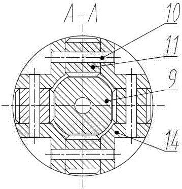
[0017] As shown in the accompanying drawings, the variable-diameter hydraulic cutter for continuous cutting of casing pipes of different diameters is realized by the rack and pinion drive, which is driven by the upper joint 1, the nozzle 2, the piston 3, the sealing ring 4, the indexing mechanism 5, and the piston. Rod 6, pin 7, upper spring 8, cylindrical rack 9, hinge pin 10, cutter 11, hard alloy teeth 12, lower spring 13 and housing 14 are characterized in that: described upper joint 1 and hydraulic cutting The knife housings 14 are connected by thread; the nozzle 2 is installed on the top of the piston push rod 6 by thread connection, the piston 3 and the piston push rod 6 are connected by thread, and the inside of the piston push rod 6 is provided with an axial through hole. The seal between the piston 3 and the housing 14 is realized by the sealing ring 4; the upper spring 8, the...


PUM


Abstract

The invention relates to a variable-diameter hydraulic cutter capable of realizing continuous cutting of sleevings with different diameters through gear and rack transmission in the abandoned well operation process. The technical scheme of the cutter is that an upper joint is connected with a housing by threads; a spraying nozzle is located in a piston push rod and connected with the push rod by the threads; an upper spring, a turning mechanism and a piston are mounted on the piston push rod sequentially and arranged inside the housing; cutter knives are arranged uniformly in the circumferential direction and connected with the housing by hinge pins, gear structures of the upper parts of the cutter knife bodies are meshed with a cylindrical rack, the rack and the gears can transmit, and too large displacement of the cutter knives is limited while the opening degrees of the cutter knives are accurately controlled. According to the variable-diameter hydraulic cutter, the piston and the turning mechanism are pushed by the throttling action, gear and rack transmission is matched so as to realize continuous cutting of the sleevings with different diameters, trip times are reduced, the abandoned well operation time is saved, and the sleeving cutting efficiency and the operation reliability in the abandoned well operation process are improved greatly.

Description

technical field [0001] The invention relates to a variable-diameter hydraulic cutter capable of continuously cutting casings of different diameters through rack and pinion transmission, which can be used for cutting casings of different specifications in the process of oil and gas exploration and production and for later well abandonment operations. Background technique [0002] In the process of exploration and development of offshore and onshore oil and gas fields, some old oil and gas wells and safety hazard wells close to the design life will appear one after another. In order to prevent oil and gas leakage from threatening the natural environment and to make more reasonable and comprehensive use of oil and gas resources, after After the oil and gas resource assessment, these oil and gas wells with no economic value and safety hazard wells that need to be abandoned after reaching the service life will be closed, and then the permanent well abandonment operation will be gr...

Claims


Application Information

Patent Timeline
Patent Type & Authority Applications(China)
IPC IPC(8): E21B29/00
CPCE21B29/005
Inventor 田家林李居瑞杨琳朱志张堂佳杨毅林晓月周思奇
Owner SOUTHWEST PETROLEUM UNIV
Learn More