Two-dimensional directing mechanism for optical remote sensing instrument

A technology of optical remote sensing and pointing mechanism, which is applied in the direction of instruments, measuring instrument components, measuring devices, etc., can solve the problems of satellite platform attitude control, increase the difficulty of processing and assembly, etc., and achieve light weight, compact structure, and favorable attitude control. Effect

Active Publication Date: 2017-09-29
SHANGHAI INST OF TECHNICAL PHYSICS - CHINESE ACAD OF SCI
View PDF7 Cites 5 Cited by
  • Summary
  • Abstract
  • Description
  • Claims
  • Application Information

AI Technical Summary

Problems solved by technology

Authorized patent number CN103471566B proposes "a scanning mechanism applied to aerial cameras", which adopts a U-shaped structure. Obviously, when the scanning mirror has a large diameter, it is difficult to balance good rigidity and light weight at the same time.
The patent application publication number CN105835057A proposes "a two-dimensional pointing mechanism for space optical remote sensing instrument" which adopts a structure combining a 45° scanning mechanism and a conical scanning mechanism. According to the description of its claims, it can be seen that the azimuth axis drive in its structure There are harmonic reducers in the components and pitch axis drive components, which increases the difficulty of processing and assembly
In addition, the moment of inertia of the azimuth axis system in the scanning or pointing mechanism in these two patents changes with the rotation of the pitch axis, which brings difficulties to the attitude control of the satellite platform

Method used


Image

  • Two-dimensional directing mechanism for optical remote sensing instrument
  • Two-dimensional directing mechanism for optical remote sensing instrument
  • Two-dimensional directing mechanism for optical remote sensing instrument

Examples


Embodiment Construction

[0029] The embodiments of the present invention will be described in detail below in conjunction with the accompanying drawings. This embodiment is implemented on the premise of the technical solution of the present invention, and detailed implementation methods and specific operating procedures are provided, but the scope of protection of the present invention is not limited to the following the described embodiment.

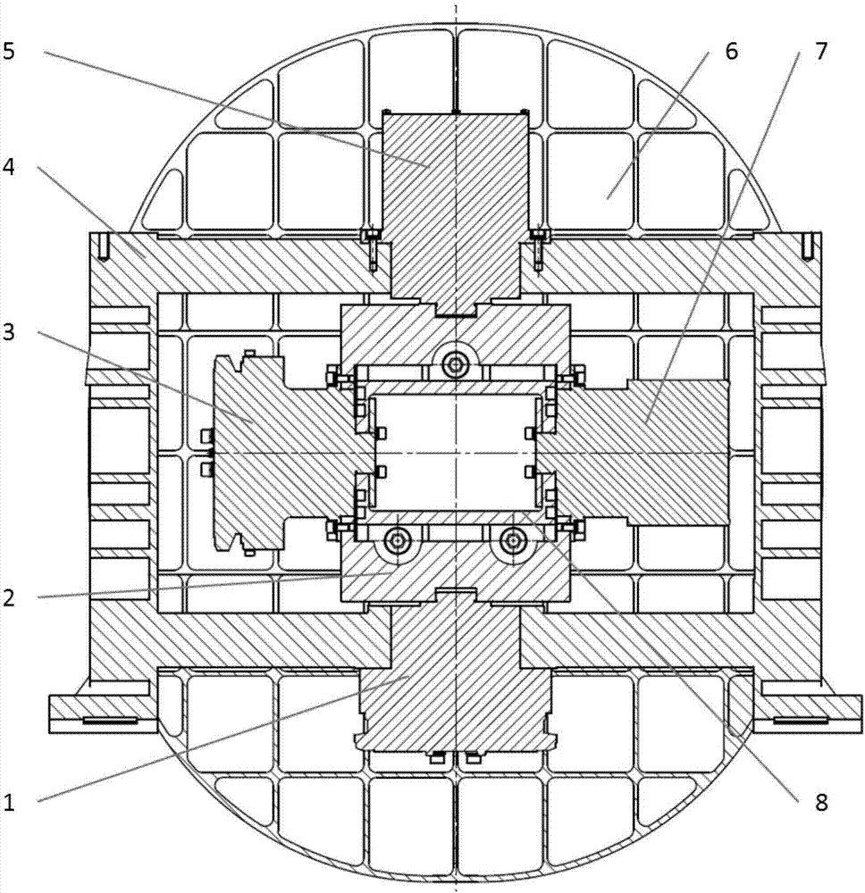
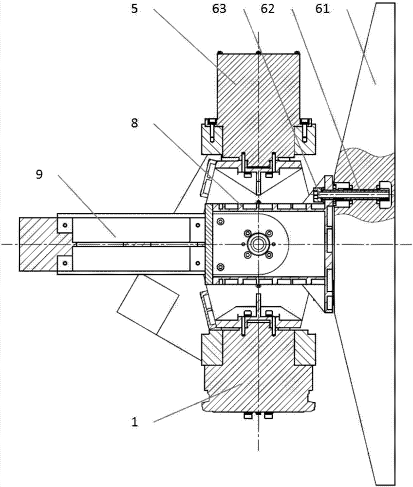
[0030] Such as figure 1 and figure 2 As shown, the two-dimensional pointing mechanism of this embodiment includes an upper half shaft assembly 5, a lower half shaft assembly 1, a left half shaft assembly 3, a right half shaft assembly 7, a pointing mirror assembly 6, an inner frame 8, an outer frame 2, a support Frame 4 and counterweight 9;

[0031] Such as figure 2 As shown, the pointing mirror assembly 6 includes a pointing mirror 61, a flexible support joint 62 and a support screw 63. The support method of the pointing mirror 61 adopts back support, and...


PUM


Abstract

The invention discloses a two-dimensional directing mechanism for an optical remote sensing instrument. The two-dimensional directing mechanism comprises an upper half shaft assembly, a lower half shaft assembly, a left half shaft assembly, a right half shaft assembly, a directing mirror assembly, an inner frame, an outer frame, a support frame and a counterweight. The lower half shaft assembly and the left half shaft assembly have the same structure. The upper half shaft assembly and right half shaft assembly have the same structure. The upper half shaft assembly, the lower half shaft assembly and the inner frame constitute a pitch axis system. The left half shaft assembly, the right half shaft assembly, the outer frame and the pitch axis system form an azimuth axis system. The two-dimensional directing mechanism is high in directing precision, light in weight, low in moment of inertia, small in interference torque of satellite platform, compact in structure, simple in structure, and directly driven to avoid a complex harmonic reducer or gear reduction mechanism, and highi in reliability.

Description

technical field [0001] The invention relates to the technical field of motion mechanisms of aerospace optical remote sensing instruments, in particular to a two-dimensional pointing mechanism for optical remote sensing instruments. Background technique [0002] With the development of the aerospace industry, the two-dimensional pointing mechanism of space optical remote sensing instruments has become more and more widely used because it can expand the observation field of view. Authorized patent number CN103471566B proposes "a scanning mechanism for aerial cameras", which adopts a U-shaped structure. Obviously, it is difficult to balance good rigidity and light weight when the scanning mirror has a large diameter. The patent application publication number CN105835057A proposes "a two-dimensional pointing mechanism for space optical remote sensing instruments" which adopts a structure combining a 45° scanning mechanism and a conical scanning mechanism. According to the descri...

Claims


Application Information

Patent Timeline
Patent Type & Authority Applications(China)
IPC IPC(8): G01D11/30
CPCG01D11/30
Inventor 邓容孙小进陈凡胜王伟成
Owner SHANGHAI INST OF TECHNICAL PHYSICS - CHINESE ACAD OF SCI
Why Eureka
Try Eureka