
Dual-band transmitting center-fed antenna of a portable high-frequency ground wave radar

A high-frequency ground wave radar, portable technology, applied in the structural connection of antennas, antenna grounding switches, and devices that enable antennas to work in different bands at the same time, can solve problems such as large and complex structures, great influence on characteristics, and unsuitability. To achieve the effect of extending the working frequency band

Active Publication Date: 2017-09-29
WUHAN UNIV
View PDF5 Cites 0 Cited by
  • Summary
  • Abstract
  • Description
  • Claims
  • Application Information

AI Technical Summary

Problems solved by technology

[0004] The traditional log-periodic antenna can work in a very wide frequency band, but its structure is huge and complex, which is completely unsuitable for portable high-frequency ground wave radar
[0005] Document 1 (Wu Shicai et al., Dual-frequency transmitting monopole antenna for portable high-frequency ground wave radar, invention patent number: ZL 2012 1 0411260.9, authorized announcement date 2015-4-29) provides a dual-frequency monopole The main lobe of the radiation pattern of each frequency is along the ground, but because the antinode of the vertical monopole radiation current is close to the ground, the characteristics of this monopole are greatly affected by the ground environment in actual use, resulting in high The performance of frequency-sounding sea radar is severely affected

Method used


Image

  • Dual-band transmitting center-fed antenna of a portable high-frequency ground wave radar
  • Dual-band transmitting center-fed antenna of a portable high-frequency ground wave radar
  • Dual-band transmitting center-fed antenna of a portable high-frequency ground wave radar

Examples


Embodiment Construction

[0071] The specific implementation manner of the "dual-band transmitting mid-fed antenna" of the present invention will be further described below in conjunction with the accompanying drawings.

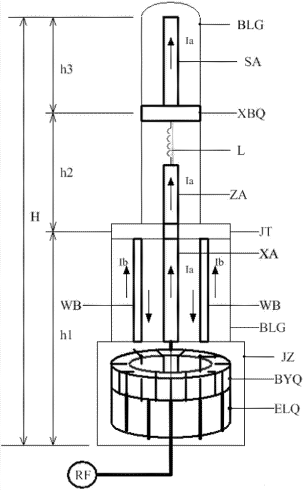
[0072] 1. Calculate the radar wavelength λ1 according to the center frequency f1 of the lower frequency band in the two operating frequency bands of the radar. According to the design requirements of the mid-fed antenna, the overall height of the antenna is H<0.5λ1. At this time, the radiation pattern of the vertical plane of the antenna is It is in the shape of "∞", without side lobes, and at the same time, the directivity pattern of the horizontal plane is omnidirectional. Starting from the highest frequency of this frequency band, H=0.3λ1 can be taken. If the height of the antenna needs to be further reduced, the antenna needs to be loaded intensively, and the loading point is set at the height of the antenna at 0.7H, avoiding the antinode of the radiation current to reduce loss, a...


PUM


Abstract

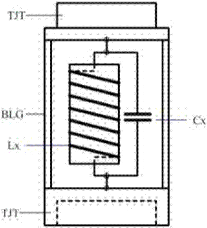
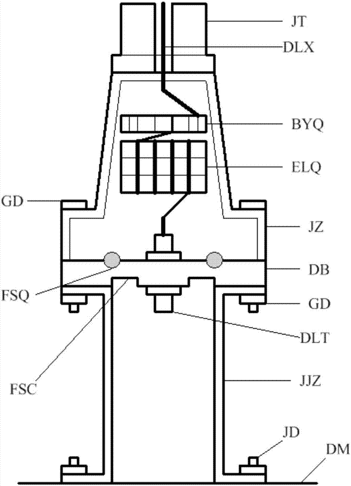
The invention discloses a dual-band transmitting center-fed antenna of a portable high-frequency ground wave radar. The dual-band transmitting center-fed antenna consists of five parts including an antenna upper section, a notch filter, an antenna middle section, an antenna lower section, and a base, wherein the notch filter is mainly formed by an inductor Lx and a capacitor Cx connected in parallel. The base includes a transmission line transformer and a cable choke coil. When radar frequency f1 is far lower than the resonant frequency of the notch filter, the notch filter is equivalent to a loading inductor, the three antenna sections form a typical center-fed antenna. When radar frequency f2 is equal to the resonant frequency of the notch filter, the notch filter presents high impedance to separate the antenna upper section so that the antenna middle section, the antenna lower section and the base are reconstructed to be a new center-fed antenna. Thus, compared with the typical center-fed antenna, the dual-band transmitting center-fed antenna has two wide operating frequency bands with the center frequencies f1 and f2 respectively, has a strongest major lobe of radiation directional diagram along the ground, and can greatly improve the comprehensive performance of high-frequency sea detection radar.

Description

technical field [0001] The present invention relates to a compact antenna system of a portable high-frequency ground wave radar, in particular to a compact antenna system characterized in that it consists of an antenna upper section SA, a wave trap XBQ, an antenna middle section ZA, an antenna lower section WB, a base Five parts such as JZ form a dual-band transmitting mid-fed antenna. Background technique [0002] The portable high-frequency sea state radar used to detect ocean surface currents, waves and wind fields uses a compact monopole as the transmitting antenna and a compact monopole cross-ring as the receiving antenna, so it does not need to open up a wide antenna field, which greatly improves the The construction and maintenance costs of radar stations are reduced, and the seaside application is very convenient and flexible. Therefore, this portable radar accounts for 90% of the total number of high-frequency ground wave radars in operation in the world today. [...

Claims


Application Information

Patent Timeline
IPC IPC(8): H01Q1/36H01Q1/50H01Q5/20H01Q23/00
CPCH01Q1/36H01Q1/50H01Q5/20H01Q23/00Y02A90/10
Inventor 吴世才李子言文必洋田应伟
Owner WUHAN UNIV
Learn More